[0012]The
advantage of the invention is the multi-band behavior of the antenna, especially the
fractal antenna which allows convenient reception of a
signal for communication. The multi-band behavior is obtained by a set of geometry patterns of the same dimension. The transparent materials may be formed by a
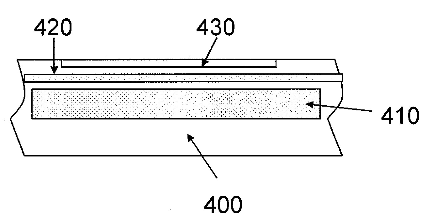
sputtering vacuum deposition process. An additional passive layer can be added to protect the conducting layer. Materials for this
passivation layer are made, for instance, of an
oxide, or any other polymeric material,
polymer,
resin coating on the structure. The method for forming the transparent conductive layer includes an
ion beam method at low temperature, see 1999, IEEE, 1191. U.S. Pat. No. 6,743,476 discloses a method of producing a
thin film electrode at
room temperature. Both the
ion beam and sputter processes are expensive. During the formation process, the present invention suggests that a
mask can be placed on the substrate material to obtain the desired multi-band antenna shape. This
mask normally is made of conducting material such as stainless steel or
copper, or a photosensitive material to create the
mask by photochemical processes. Then, the pattern can be “print” on the desired object. Thus, the expensive sputter process can be replaced by the
chemical solution coating.
[0013]An antenna
system includes a
driven element, and at least one element a portion of which is a fractal element selected from a fractal counterpoise element. Wherein the fractal element is superposition over at least N=1 iterations of a fractal generator motif. An iteration is placement of the fractal generator motif upon a base figure through at least one positioning selected from the group consisting of (i) rotation, (ii) stretching, and (iii) translation.
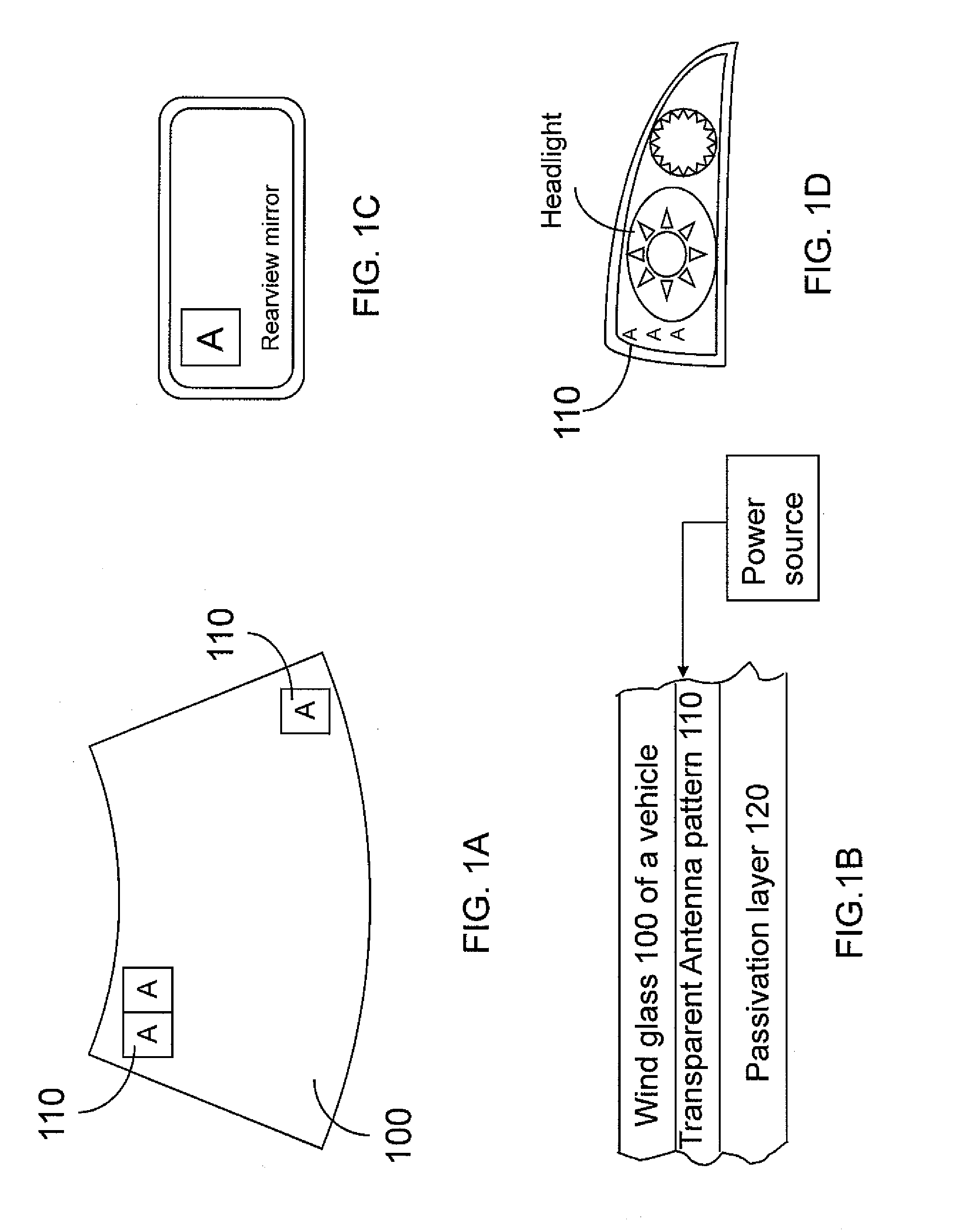
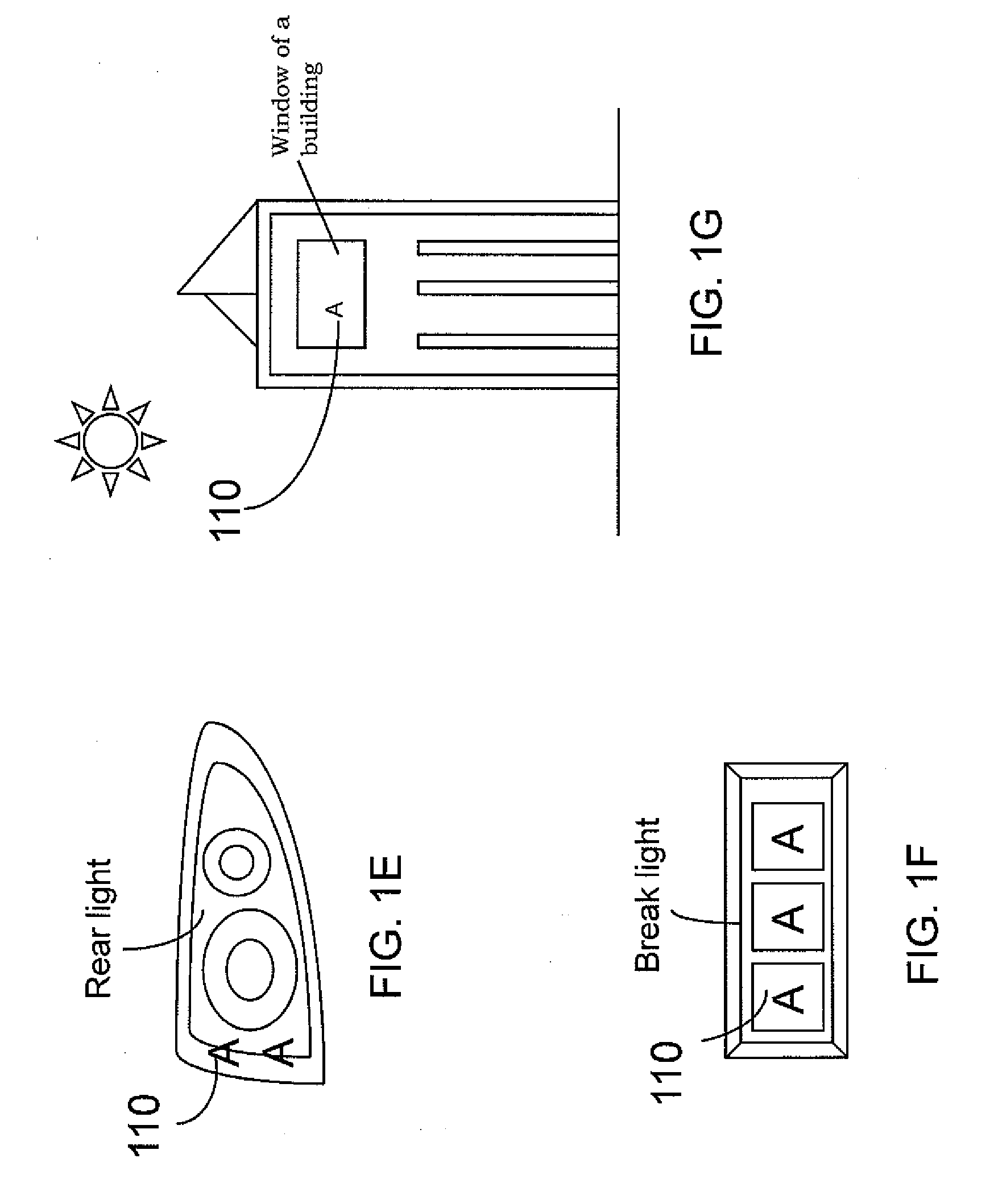
[0014]The antenna comprises a conductive pattern having an antenna configuration, wherein said conductive pattern is formed of conductive carbon, a
conductive polymer or conductive glue having glass and conductive particles. The conductive pattern includes one or more particles selected from Au, Zn, Ag, Pd, Pt, Rh, Ru, Cu, Fe, Ni, Co, Sn, Ti, In, Al, Ta, Ga, Ge and Sb. The conductive carbon includes CNT. The
conductive polymer includes polythiophenes, poly(selenophenes), poly(tellurophenes), polypyrroles, polyanilines. The conductive glue includes glass, conductive particles, additive. The glass is selected from Al2O3, B2O3, SiO2, Fe2O3, P2O5, TiO2, B2O3 / H3BO3 / Na2B4O7, PbO, MgO, Ga2O3, Li2O, V2O5, ZnO2, Na2O, ZrO2, TlO / Tl2O3 / TlOH, NiO / Ni, MnO2, CuO, AgO, Sc2O3, SrO, BaO, CaO, Tl and ZnO.
[0015]The antenna pattern includes
fractal antenna configuration, monopole,
dipole antenna configuration, battlements shape, trapezoidal planar antenna configuration, and inverted F configuration.
[0016]The conventional antenna is attached on the
printed circuit board (PCB) of the device. However, the signal and EM
waves generated by the antenna and the PCB will interrupt each other. Therefore, one aspect of the present invention is to remove the antenna from the PCB in order to eliminate the interference. In the embodiment, the antenna is formed on an interior or exterior surface of a housing of an electronic device having a
printed circuit board, wherein a shielding structure is disposed between said antenna and said shielding structure; wherein said antenna has a conductive pattern, and is formed of metallic material, conductive carbon, a
conductive polymer or conductive glue having glass and conductive particles.

