
F-inverted compact antenna for wireless sensor networks and manufacturing method

a wireless sensor network and compact antenna technology, applied in the direction of helical antennas, non-resonant long antennas, waveguide devices, etc., can solve the problems of power, size, cost and sensing, inability to collect smartdust and reuse, and antennas requiring a large ground plane are not compatible with smartdust and cannot be applied in these areas. achieve maximum efficiency and bandwidth

Inactive Publication Date: 2010-02-04
UNIV OF MARYLAND
View PDF5 Cites 238 Cited by
  • Summary
  • Abstract
  • Description
  • Claims
  • Application Information

AI Technical Summary

Benefits of technology

[0015]It is therefore an object of the present invention to provide a compact antenna compatible with ultra-low volume Wireless Sensor Network applications for highly integrated transceivers having an omnidirectional radiation pattern and optimized for maximum efficiency and bandwidths which are compatible with the antenna's miniature dimensions.
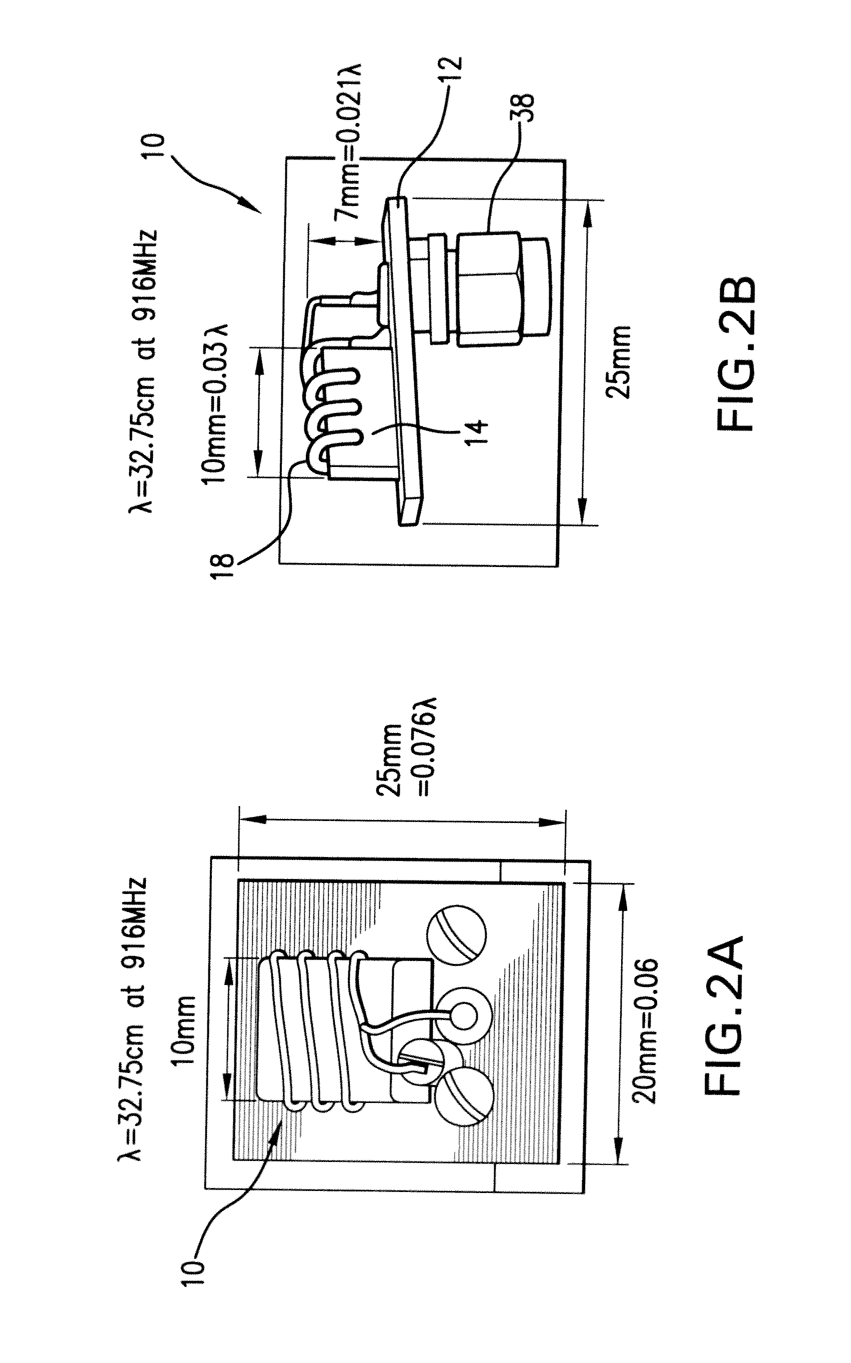
[0016]It is a further object of the present invention to provide a low profile compact antenna with a ground plane size as small as few percent of the resonance wavelength and which is easily scalable for a broad range of frequencies such as 916 MHz-2500 MHz bands while maintaining satisfactory performance.
[0017]It is still an object of the present invention to provide an electrically small antenna with a design which balances the trade offs in terms of communication distance, stringent geometrical size limits, bandwidths and antenna efficiency.

Problems solved by technology

However, in some Wireless Sensor Network (WSN) systems, such as the Smart Dust systems, different application constraints are employed.
The key challenges of the SmartDust prototyping are power, size, cost and sensing.
They are usually disposable simply because it is not practical to collect SmartDusts and reuse them.
Obviously, antennas requiring a large ground plane are not compatible with SmartDusts and cannot be applied in these areas.
First, in each WSN transceiver node, all components, such as sensor, antenna, battery, transceiver integrated circuit (IC), as well as the reference ground plane (normally a printed circuit board) for IC and antenna are to be stacked or integrated in a package with a total volume of only a few mm3 to one cm3, where only a fraction of this volume is left for an antenna. The millimeter or centimeter scale dimensions are often much less than a quarter wavelength at the operating frequency (i.e., 0.1λ or less). For example, in conventional ESA designs, a ground plane with a minimum quarter wavelength dimension is often necessary for proper performance. In the ISM bands (916 / 828 / 433 MHz), this ground plane size is between 8 to 16 cm. Though this is a reasonable size to be fit within a cell phone or a PDA's housing, it is too large to be integrated into SmartDust sensor nodes in WSN communication package, whose node size is on the order of a few cm3 or smaller. A package with a low height and a large ground plane area is not suitable for WSN applications. In WSN, the ground plane size must be decreased as well as the height of the antenna. This requires new designs to reduce both factors and keep the antenna highly functional.
Second, in WSN / SmartDust applications, a large amount of transceiver nodes are distributed randomly. These transceiver nodes, as well as the antennas associated with them, are oriented in various directions and form an autonomous communication network. Each communication node in this network is a complete self powered transceiver node, which requires the antenna to have a radiation pattern as omnidirectional as possible to transmit and receive signals from all directions due to the random orientation of the nodes.
Third, there is no need for a base station in WSN / Smart Dust applications. Any node in the network may serve as a base station. These nodes cover a large communication range by multi-hops. The communication distance is determined mainly by the separation of nodes, and can range from 1 to 10 m. Therefore, the gain of antenna is traded against the volume requirement.

Method used


Image

  • F-inverted compact antenna for wireless sensor networks and manufacturing method
  • F-inverted compact antenna for wireless sensor networks and manufacturing method
  • F-inverted compact antenna for wireless sensor networks and manufacturing method

Examples


Embodiment Construction

[0048]Several fundamental limitations of electrically small antennas are taken into consideration and explored to guide the design of the compact antenna 10 of the present invention. First, Radiation Resistance (Rr) is analyzed which decreases by the square of the height of the antenna. For example, the typical Radiation Resistance (Rr) of an antenna with a height of λ / 20 above a ground plane is only a fraction of an Ohm. Without a proper matching network, transferring power into and from a standard 50 Ohm port becomes practically impossible. Given this limitation, maximizing the possible height of the antenna proves to be critical for achieving proper power transfer in small antenna design.

[0049]The small size of an antenna not only limits the Rr, but also increases the capacitive input reactance, and a large inductive tuning reactance L is needed to bring the resonance frequency to the desired value. The quality factor can be expressed as Q=ωL / Rr, where ω is a resonance frequency....


PUM

PropertyMeasurementUnit
Lengthaaaaaaaaaa
Diameteraaaaaaaaaa
Diameteraaaaaaaaaa

Abstract

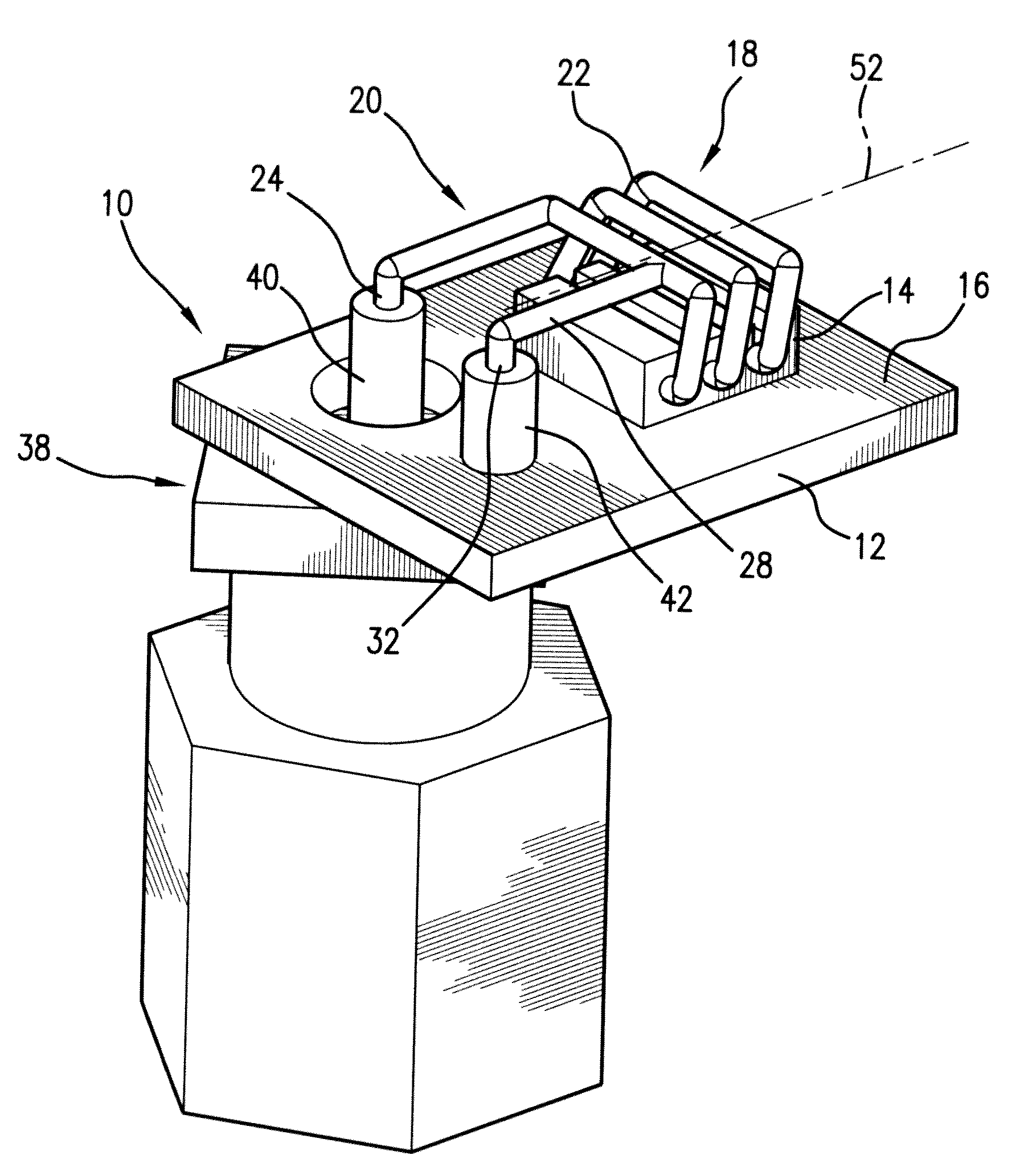
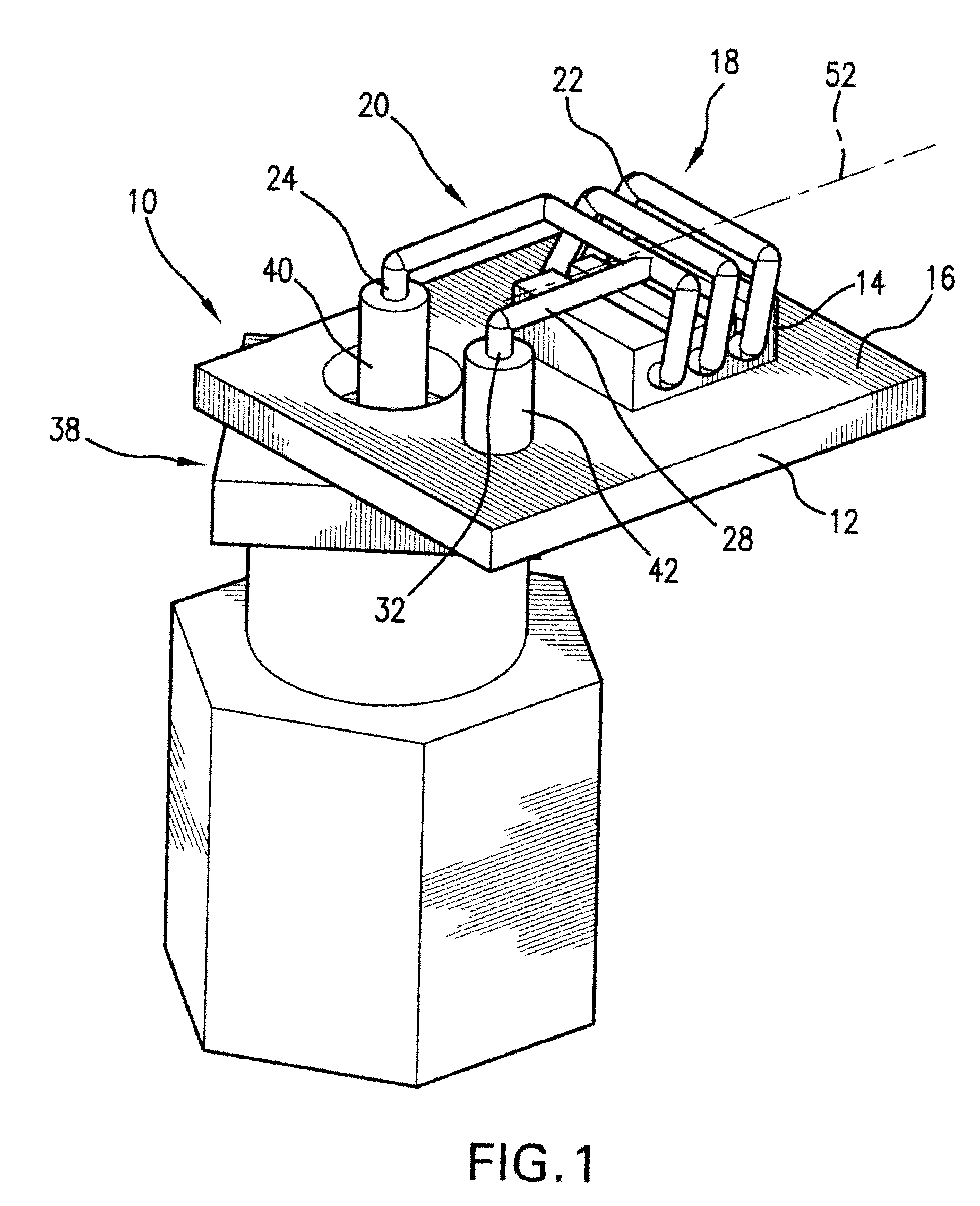
An F-inverted compact antenna for ultra-low volume Wireless Sensor Networks is developed with a volume of 0.024λ×0.06λ×0.076λ, ground plane included, where λ is a resonating frequency of the antenna. The radiation efficiency attained is 48.53% and the peak gain is −1.38 dB. The antenna is easily scaled to higher operating frequencies up to 2500 MHz bands with comparable performance. The antenna successfully transmits and receives signals with tolerable errors. It includes a standard PCB board with dielectric block thereon and helically contoured antenna wound from a copper wire attached to the dielectric block and oriented with the helix axis parallel to the PCB. The antenna demonstrates omnidirectional radiation patterns and is highly integratable with WSN, specifically in Smart Dust sensors. The antenna balances the trade offs between performance and overall size and may be manufactured with the use of milling technique and laser cutters.

Description

REFERENCE TO RELATED APPLICATIONS[0001]This utility patent application is based on Provisional Patent Application Ser. No. 61 / 055,518 filed 23 May 2008.[0002]The work was funded by NSA Contract Number H9823004C0490. The United States Government has certain rights to the invention.FIELD OF THE INVENTION[0003]The present invention is directed to Wireless Sensor Networks (WSNs) and in particular, to a compact antenna compatible with ultra-low volume Wireless Sensor Network applications.[0004]More in particular, the present invention is directed to a compact antenna for highly integrated transceivers having an omni-directional radiation pattern optimized for maximum efficiency and bandwidth.[0005]Still further, the present invention is directed to a low profile F-inverted compact antenna (FICA) for Wireless Sensor Networks with reduced size and acceptable gain and bandwidth performance achieved by “bended” helix design of the antenna element with the axis parallel to the antenna's groun...

Claims


Application Information

Patent Timeline
IPC IPC(8): H01Q1/36H01P11/00H01Q1/48
CPCH01Q9/0421Y10T29/49016H01Q11/08H01Q9/0471
Inventor YANG, BOVANIN, FELICE M.SHAO, XIBALZANO, QUIRINOGOLDSMAN, NEIL
Owner UNIV OF MARYLAND
Learn More