Apparatus for intra-ocular injection

a technology for intraocular injection and apparatus, which is applied in the field of apparatus for intraocular injection, can solve the problems of undesired systemic toxicities, inability to achieve or maintain adequate levels of drugs through oral or parenteral administration, and inability to provide effective levels of drugs specifically to the eye, etc., and achieve the effect of precise positioning of guiding means

Inactive Publication Date: 2010-02-04
FOVEA PHARMA +1
View PDF17 Cites 100 Cited by
  • Summary
  • Abstract
  • Description
  • Claims
  • Application Information

AI Technical Summary

Benefits of technology

[0019]The cut-out serves as a reference to position the guiding means with respect to the limbus, delimiting the cornea and the sclera of the eye. Therefore, the position of the guiding means is adjusted with respect to the limbus (not with respect to the centre of the iris). This feature allows precise positioning of the guiding means, even in case of cornea of non-standard diameter.

Problems solved by technology

However, delivery of drugs, proteins and the like to the eye(s) of mammals so as to achieve the desired therapeutic or medical effect, especially to the retina and / or the choroids, has proven to be challenging, most of which is owed to the geometry, delicacy and / or behavior of the eye and its components.
Oral ingestion of a drug or injection of a drug at a site other than the eye can provide a drug systemically however such a systemic administration does not provide effective levels of the drug specifically to the eye.
In many ophthalmic disorders involving the retina, posterior tract, and optic nerve, adequate levels of the drug cannot be achieved or maintained by oral or parenteral routes of administration.
Such further and repeated administrations of such drugs, however, may produce undesired systemic toxicity.
This route of administration (i.e., topical administration), however, is only effective in treating problems involving the superficial surface of the eye and diseases that involve the cornea and anterior segment of the eye, such as for example, conjunctivitis.
Topical administration of drugs is ineffective in achieving adequate concentrations of a drug(s) in the sclera, vitreous, or posterior segment of the eye.
In addition, topical eye drops may drain from the eye through the nasolacrimal duct and into the systemic circulation, further diluting the medication and risking unwanted systemic side effects.
Furthermore, delivery of drugs in the form of topical eye drops is also of little utility because the drug cannot cross the cornea and be made available to the vitreous, retina, or other subretinal structures such as the retinal pigment epithelium (“RPE”) or choroidal vasculature and / or is highly unstable and therefore not easily formulated for topical delivery.
Direct delivery of drugs to the eye by a topical insert has also been attempted however this method is not desirable.
Consequently, this technique demands a certain degree of manual dexterity that can be problematic for geriatric patients who are particularly susceptible to certain eye disorders that appear age related (e.g., age related macular degeneration).
Also, in many instances such topical inserts may cause eye irritation and such inserts are prone to inadvertent loss due to eyelid laxity.
In addition, these devices provide a source of drug only to the cornea and anterior chamber, and thus do not provide any pharmacologic advantage over topical eye drops or ointments.
Thus, such devices have limited, if any at all, utility for providing an effective source of drugs to the vitreous or tissues located in the posterior segment of the eye.
Such a procedure requires high technical skills and lots of practice.
For this reason, many non-qualified ophthalmologists are not able to carry out such operations.
In particular, perforation of the tissues can cause leakage of the injected composition out of the eye though the orifice created by the needle.
Moreover, perforation of the tissues can also favour penetration of germs into the eye, causing ocular infections.
However, such an apparatus is not very easy to handle, as the ophthalmologist must maintain the apparatus with one hand while operating the syringe with the other hand.
Moreover, in such an apparatus, the plaque is necessarily bulky, as it must covers all the exposed surface of the eye.
And finally, as the plaque is centred on the iris, the apparatus is not adapted to an eye having a cornea of non-standard diameter.

Method used


Image

  • Apparatus for intra-ocular injection
  • Apparatus for intra-ocular injection
  • Apparatus for intra-ocular injection

Examples


first embodiment

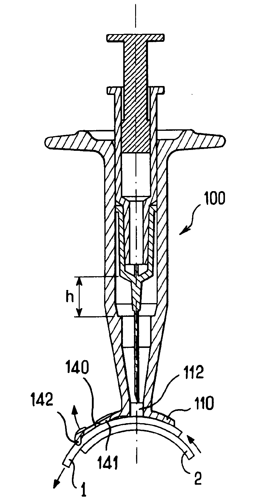
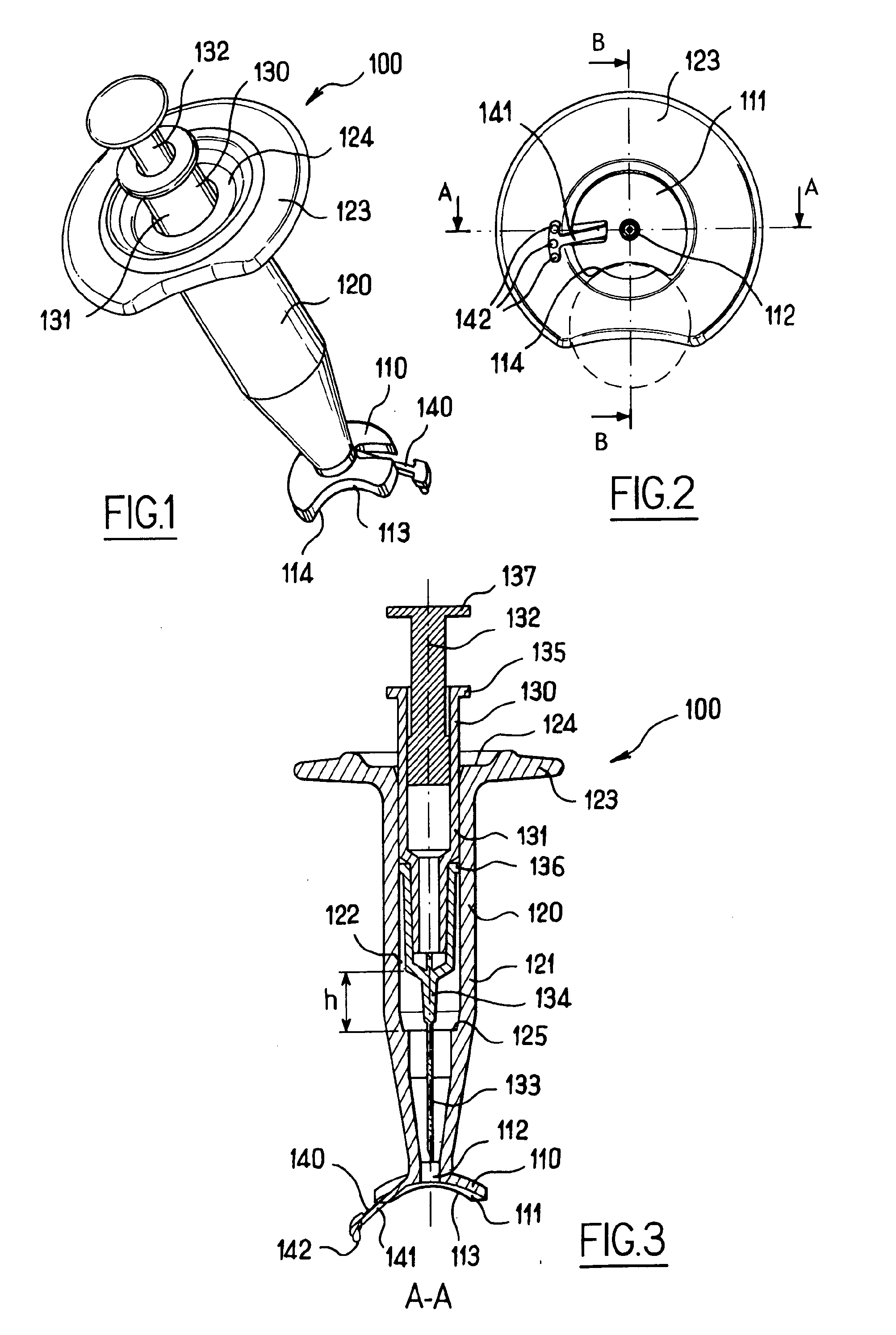
[0050]FIGS. 1 to 3 illustrate an apparatus 100 for intra-ocular injection according to the invention. The apparatus 100 comprises a plate 110 adapted for being brought into contact with an eye, a support 120 for receiving a syringe and optionally a syringe 130. The plate 110 has an eye bearing surface 111 having a curved shape for matingly bearing on the outer surface of the eye and an aperture 112 provided in the plate 110 for allowing a needle to pass through the plate 110.

[0051]Moreover, the plate 110 has a cut-out 113 having an edge 114 with a curved shape. More precisely, the edge of the cut-out has a substantially circular shape which corresponds to a shape of a limbus (as shown in dofted line on FIG. 2) so that the edge 114 can be superimposed on the limbus. The cut-out 113 has a diameter of about 12 millimetres. The cut-out serves as a reference for precisely positioning the apparatus with respect to the eye in order to perform an intra-ocular injection. The cut-out 113 is p...

second embodiment

[0068]FIGS. 10 to 13 illustrate an apparatus 200 for intra-ocular injection according to the invention. The apparatus 200 is similar to the apparatus 100, except that it comprises releasable connecting means 250 for connecting the syringe plunger and the syringe barrel. The apparatus 200 comprises a plate 210, a support 220 and a syringe 230. The plate 210 has an eye bearing surface 211, an aperture 212 and a cut-out 213 having an edge 214.

[0069]The support 220 comprises a hollow body 221 extending over the aperture 212 and comprising an inner guiding channel 222 adapted for receiving the syringe 230 in such a way that the syringe 230 can slide into the guiding channel 222. The support 220 comprises an annular flange 223 which projects outwardly from the body 221, in a radial direction relative to the axis of the guiding channel 222. The annular flange 223 allows an operator to retain the support when sliding the syringe 230 relative to the body 221. The support 220 also comprises a...

third embodiment

[0077]FIGS. 16 to 22 illustrate an apparatus 300 for intra-ocular injection according to the invention. The apparatus 300 is similar to the apparatus 200, except that it comprises a carpule and a removable safety ring for preventing movement of the needle relative to the body. The apparatus 300 comprises a plate 310, a support 320 and a syringe 330. The plate 310 has an eye bearing surface 311, an aperture 312 and a cut-out 313 having an edge 314.

[0078]The support 320 comprises a hollow body 321 extending over the aperture 312 and comprising an inner guiding channel 322 adapted for receiving the syringe 330 in such a way that the syringe 330 can slide into the guiding channel 322. The support 320 comprises an annular flange 323 which projects outwardly from the body 321, in a radial direction relative to the axis of the guiding channel 322. The annular flange 323 allows an operator to retain the support when sliding the syringe 330 relative to the body 321. The support 320 also comp...


PUM


Abstract

The application relates to an apparatus for intraocular injection comprising a plate adapted for being brought into contact with an eye and guiding means for guiding a needle into the interior of an eye, characterized in that the plate comprises a cut-out having an edge adapted to be positioned along the limbus delimiting the cornea and the sclera of the eye, so as to adjust the position of the guiding means with respect to the limbus.

Description

CROSS-REFERENCE TO RELATED APPLICATIONS[0001]This application is a National Phase Entry of International Application No. PCT / EP2008 / 050203, filed Jan. 9, 2008, which claims priority to European Application No. 07360002.5, filed on Jan. 9, 2007 and European Application No. 07360001.7, filed on Jan. 9, 2007, all of which are incorporated by reference herein.FIELD OF THE INVENTION[0002]The present invention relates to apparatus and methods for treating eyes, such as eyes of mammals having eye disorders or diseases, more particularly to apparatus and methods for administering a therapeutic medium or agent intravitreously, yet more particularly to apparatus and methods for administering such therapeutics or agents to the tissues of the eye so that the pharmaceutical action of the such therapeutics / agents is localized at the choroid and the retina, or at the ciliary body or the lens.BACKGROUND OF THE INVENTION[0003]There are a number of vision-threatening disorders or diseases of the eye ...

Claims


Application Information

Patent Timeline
Patent Type & Authority Applications(United States)
IPC IPC(8): A61M5/42
CPCA61F9/0017A61M5/427A61M5/3287
Inventor PAQUES, MICHELROY, PIERRE
Owner FOVEA PHARMA
Why Eureka
Try Eureka