
Disc filter sector and disc filter

a technology of disc filter and sector, which is applied in the field of disc filter, can solve the problems of weakening the filtering capacity of the filter, and achieve the effects of easy and quick installation, easy machinability, and fast and simple sector assembly

Active Publication Date: 2010-02-11
METSO FABRICS INC
View PDF7 Cites 5 Cited by
  • Summary
  • Abstract
  • Description
  • Claims
  • Application Information

AI Technical Summary

Benefits of technology

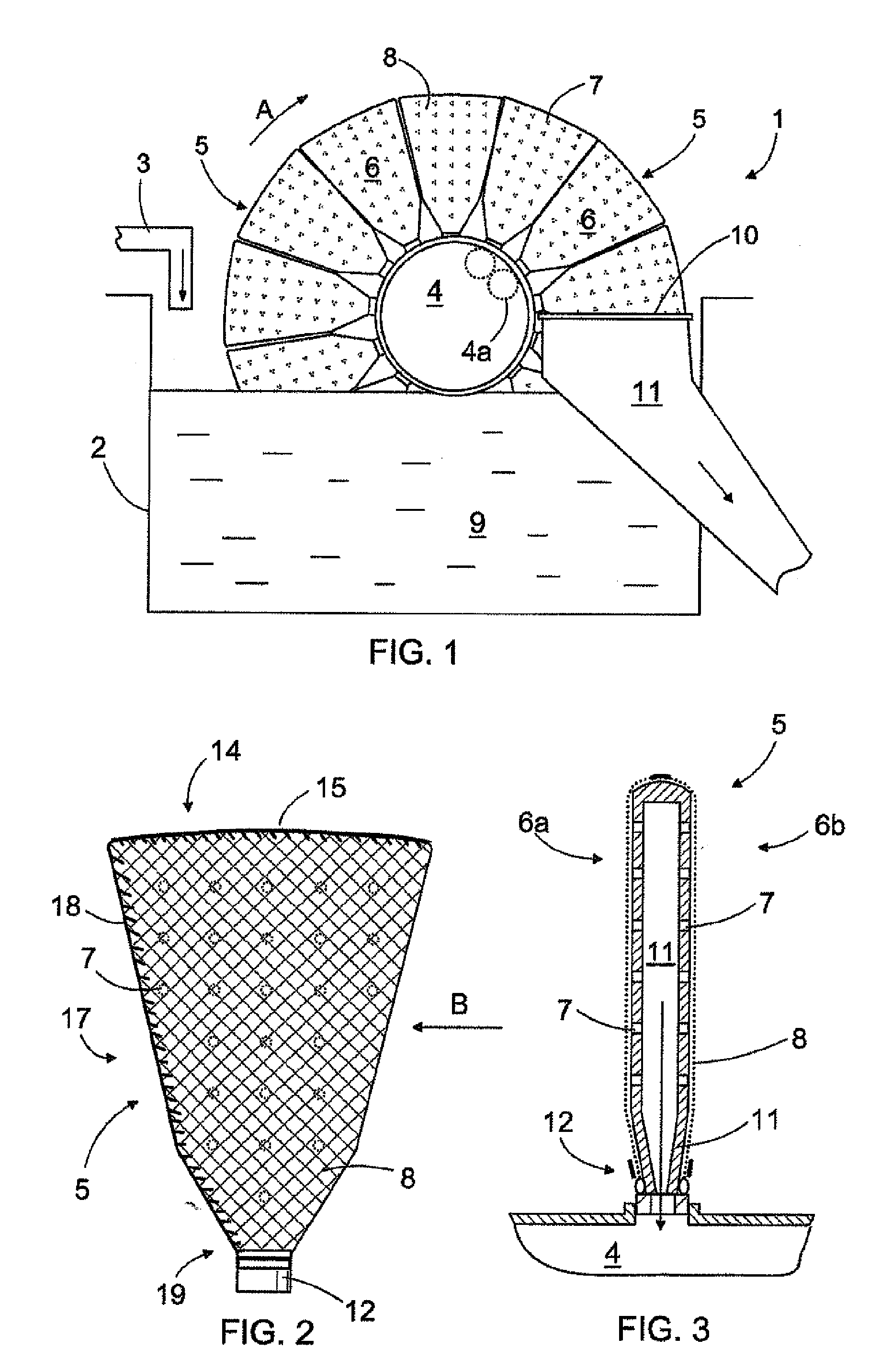
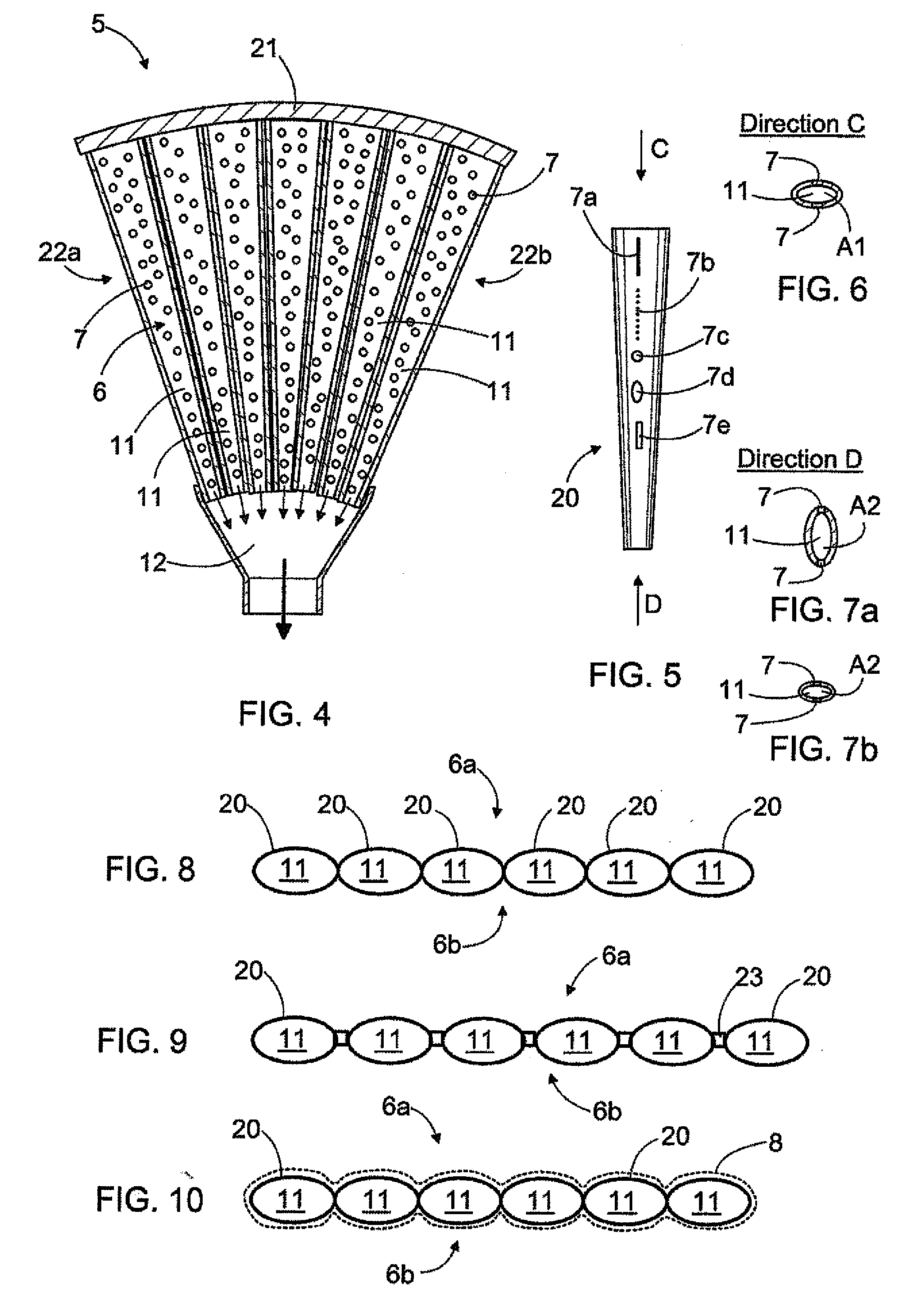
[0008]The invention provides the advantage that the flow of the filtered liquid inside the sector towards the neck section becomes more controlled when it occurs in two or more separate flow channels. A separating wall between the flow channels prevents the filtered liquid to flow inside the sector in the direction transverse to the radial direction, thus preventing problems that occur especially when the sector rises from a basin. Another advantage is that the walls between the flow channels act as radial reinforcements in the sector. The walls receive the compression load directed to the side surfaces of the sector and further reinforce the sector against bending forces and torsional load. Separate reinforcements are then not necessarily needed. Thus, there are no extra structures inside the flow channels to cause flow resistance. Therefore, the structure of the invention permits a smooth flow from the openings of the side surfaces to the neck section. An efficient flow of the liquid phase filtered inside the sector improves the filtering efficiency of the disc filter. Further, because the sector can quickly and thoroughly be emptied of liquid, the disc filter can produce a drier than before and good-quality solid matter that will not necessarily need any additional drying in later steps of the process.
[0025]The idea of an embodiment is that the sector is made of one or more components that are at least mainly made of plastic material. The advantage of plastic is that it is light, strong, inexpensive, easily machinable, and endures chemical stress well. The plastic material can, if necessary, be reinforced with reinforcement fibres or the like. The components can be made by injection-moulding, moulding, rotation moulding, thermoforming or chip-removing machining. The flow openings can be made with cores, if necessary. Injection-moulding is well suited for mass-production, whereas rotation moulding permits the making of even small batches economically.

Problems solved by technology

A problem with the present sector elements is that the flow from inside the sector element to the neck section and on to the body is not efficient enough, which weakens the filtering capacity of the filter.

Method used


Image

  • Disc filter sector and disc filter
  • Disc filter sector and disc filter
  • Disc filter sector and disc filter

Examples


Embodiment Construction

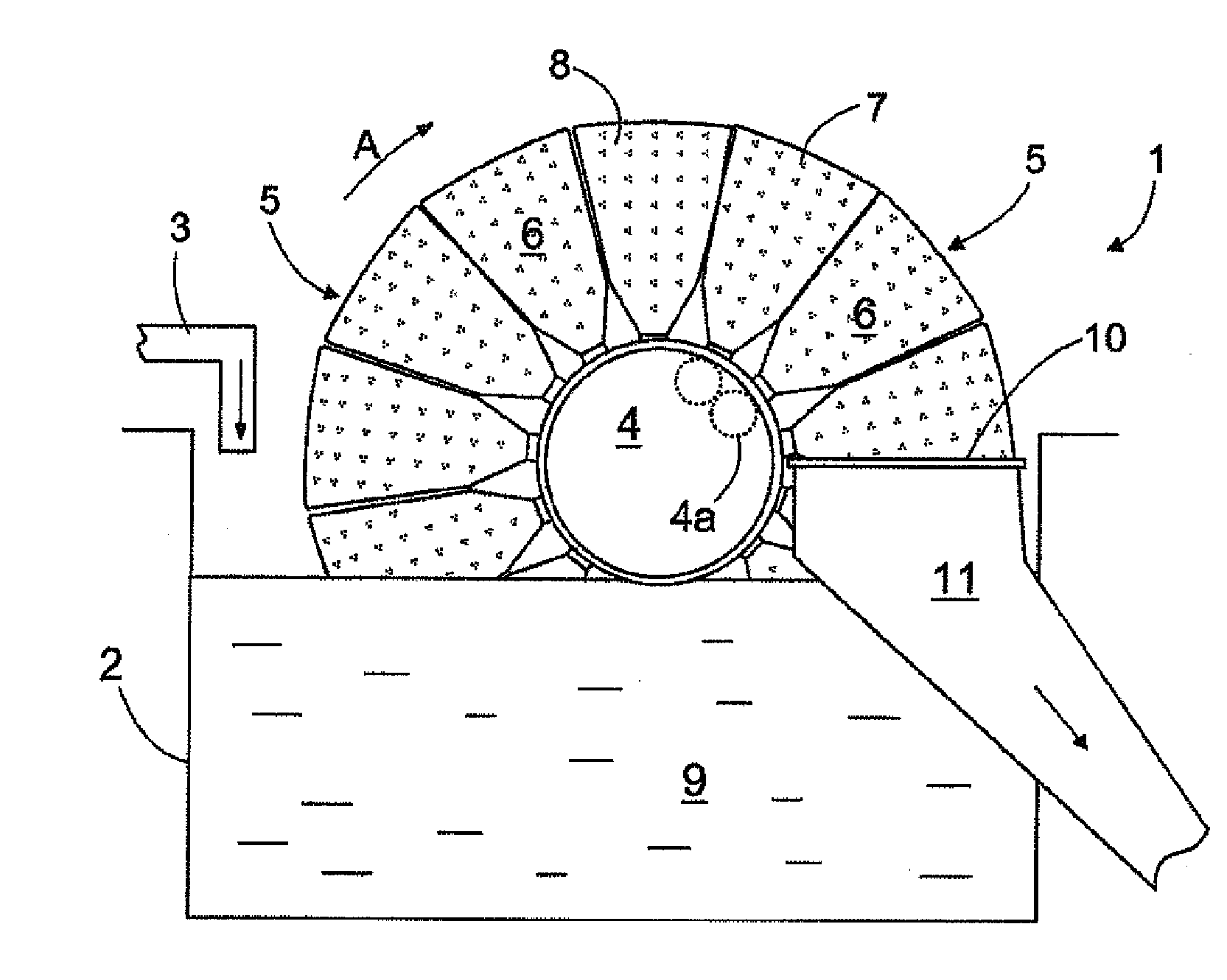
[0053]FIG. 1 shows a disc filter 1 that comprises a basin 2 to which a solution formed by solid matter and liquid is led from a supply channel 3. It should be noted that the level of the solution in the basin 2 is typically lower than in the case shown in FIG. 1. Further, the disc filter 1 comprises a body 4 rotatable around a horizontal axis. The body 4 can be made of one tubular piece or alternatively of several pipes 4a. On the outer circumference of the body 4, several essentially triangular sectors 5 are placed side by side so that the sectors 5 form a relatively narrow disc-like structure around the body 4. One body 4 can comprise several disc-like structures of this type arranged at a desired distance from each other in the axial direction. The triangular side surfaces 6 of each sector 5 have openings 7. A filter fabric 8 or the like can be arranged against the side surface to act as a filtering layer. The body 4 of the disc filter is rotated around its longitudinal axis in d...


PUM

PropertyMeasurementUnit
Flow rateaaaaaaaaaa
Lengthaaaaaaaaaa
Sizeaaaaaaaaaa

Abstract

A disc filter includes several triangular sectors that are connected from their neck section to the body of the disc filter. The sectors form a relatively thin disc that is rotated during filtration in a basin that contains a suspension to be filtered. The side surfaces of the sector have openings through which liquid in the suspension passes into several essentially radial flow channels inside the sector to flow on to the neck section and away from the sector. A separating wall is formed between two adjacent radial flow channels. Furthermore, the sector is made of two side elements which are of plastic material and the mating surfaces of which are placed against each other.

Description

BACKGROUND OF THE INVENTION[0001]The invention relates to a disc filter and its sector. A disc filter has several essentially triangular sectors that form a relatively thin disc that is rotated in a basin containing a suspension to be filtered. The sector comprises opposing side surfaces with several openings through which liquid filtered from the suspension can enter a flow channel inside the sector and on through a neck section of the sector to the body of the disc filter. Solid matter stays against the outer surface of the sector, from which it is removed to a discharge shaft at the end of the filtering step. The object of the invention is described in more detail in the preambles of the independent claims.[0002]For instance in mining industry, metal processing, chemical industry, and in the processes of foodstuff and pharmaceutical manufacturing, there is a need for solid-liquid filtering, in which liquid and solid particles are separated from a suspension of solid matter and li...

Claims


Application Information

Patent Timeline
IPC IPC(8): B01D33/23
CPCB01D2201/4084B01D33/23
Inventor SERVO, MATTISERVO, IRMA
Owner METSO FABRICS INC
Learn More