Thin film magnetic head having a pair of magnetic layers whose magnetization is controlled by shield layers

a shield layer and magnetic head technology, applied in the field of thin film magnetic heads, can solve the problems of inability to improve the the most appropriate nonmagnetic middle layer, and the material utilizing as a nonmagnetic middle layer is limited, so as to achieve a low rate of change in magnetoresistance, reduce the reading gap, and increase the effect of magnetization resistance resistan

Active Publication Date: 2010-02-18
TDK CORPARATION
View PDF9 Cites 46 Cited by
  • Summary
  • Abstract
  • Description
  • Claims
  • Application Information

AI Technical Summary

Benefits of technology

[0007]The present invention targets a thin film magnetic head having a magneto-resistance (MR) laminated body where a first MR magnetic layer (free layer) whose direction of magnetization is changed according to an external magnetic field, a nonmagnetic middle layer and a second MR magnetic layer (free layer) whose direction of magnetization is changed according to the external magnetic field are arranged in respective order by making contact with each other, and a bias magnetic field applying means that is established on an opposite surface from the ABS of the MR laminated layer, and that applies a bias magnetic field in a direction at right angles to the ABS to the MR laminated body. The objective of the present invention is to provide a thin film magnetic head where a high rate of change in magnetization resistance can be obtained by controlling the directions of magnetization of two MR magnetic layers in non-magnetic field state to antiparallel directions to each other not depending upon a magnetic interaction between these MR magnetic layers, and the rate of change in magnetization resistance varies less, and reduction of read gap is easy.
[0010]In addition, since the first and second antiferromagnetic layers and the first and second exchange coupling magnetic field application layers also have a function as a shield layer, respectively, they contribute to the reduction of the read gap. The present invention is featured such that the shield layer that is not magnetically coupled with the MR magnetic layers conventionally is magnetically coupled with the MR magnetic layer.
[0012]This is because the number of grains that can be accommodated in the projection area whose film area has restriction is limited and since each grain is magnetized along the magnetization easy axis, an average magnetization orientation varies. As a result, the direction of magnetization of the second exchange coupling magnetic field application layer varies within a projection area, and a direction of magnetization of the second MR magnetic layer also tends to vary. However, since the exchange coupling intensity in a peripheral area where a film area is easily secured and variation of a macro in the direction of magnetization is small is set relatively high; in other words, the exchange coupling intensity in the projection area is set relatively low, the effect of variation in the direction of magnetization of the second antiferromagnetic layer in the projection area is relatively reduced and the direction of magnetization in the non-magnetization state in the second MR magnetic layer is stabilized and the variation of the rate of change in magnetoresistance is controlled.
[0014]As described above, a thin film magnetic head where a high rate of change in magnetization resistance can be obtained, and variation in the rate of change in magnetization resistance is small and reduction of the read gap is easy can be provided.

Problems solved by technology

However, in the thin film magnetic head with a method where two free layers are magnetically tied due to the RKKY interaction, a material utilizing as a nonmagnetic middle layer is limited and the improvement of a rate of change in magnetoresistance cannot also be expected.
For example, Cu shows the RKKY effect and has superior spin conduction; however, because the resistance is too low, it is not the most appropriate as a nonmagnetic middle layer in the film configuration using the two free layers.

Method used


Image

  • Thin film magnetic head having a pair of magnetic layers whose magnetization is controlled by shield layers
  • Thin film magnetic head having a pair of magnetic layers whose magnetization is controlled by shield layers
  • Thin film magnetic head having a pair of magnetic layers whose magnetization is controlled by shield layers

Examples


example 1

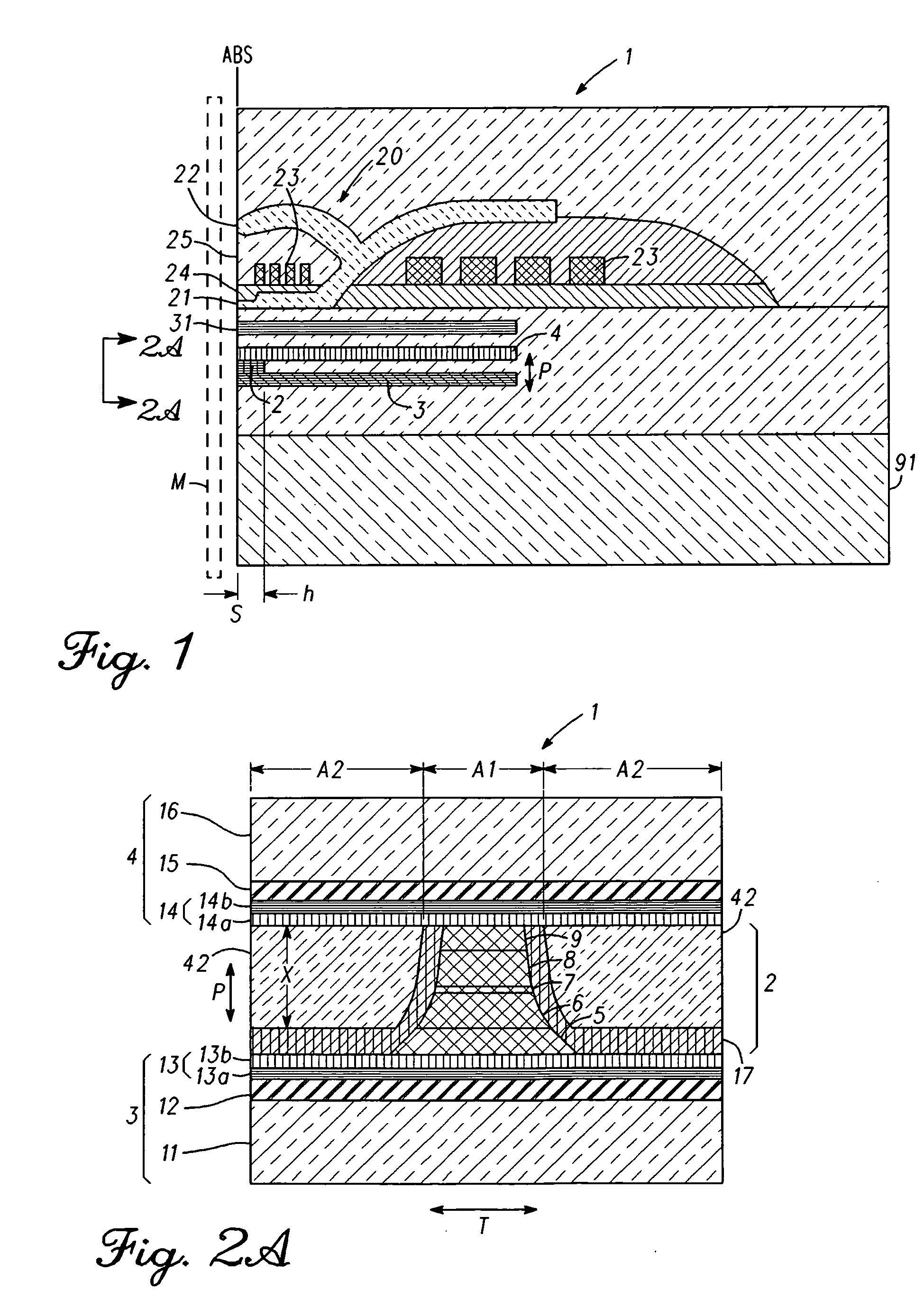
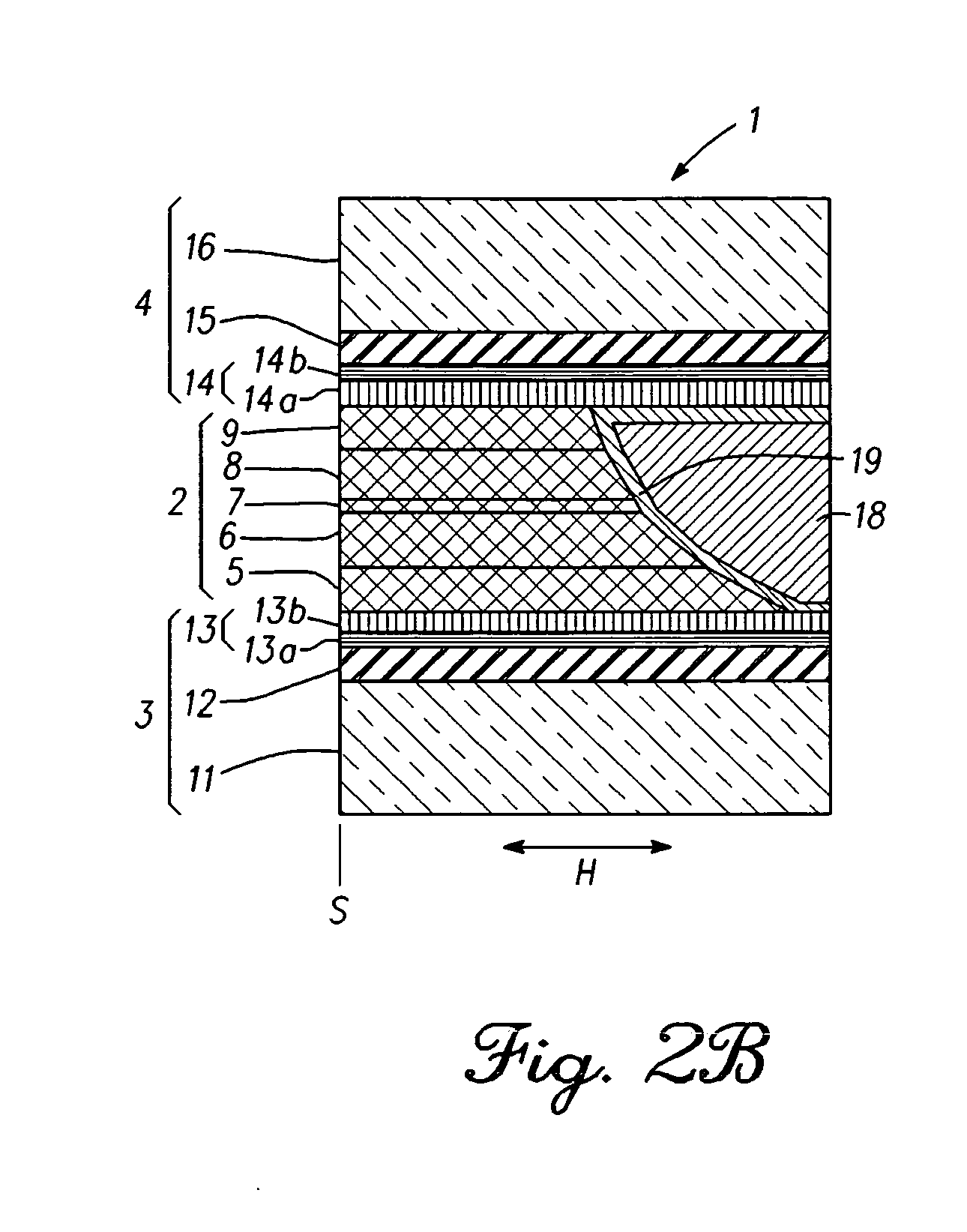
[0071]After the first main shield layer 11 (NiFe) is formed using a plating method, a foundation layer (NiFe0.5 nm, not shown), the first antiferromagnetic layer 12 (IrMn 5 nm), the first exchange coupling magnetic field application layer 13 (CoFe 2.0 nm / NiFe 4.0 nm), the first magnetic coupling layer 5 (Ru 0.7 nm / CoFe 1.0 nm / Ru 0.7 nm / CoFe 1.0 nm / Ru 0.7 nm), the first MR magnetic layer 6 (NiFe 4.0 nm / CoFe 2.0 nm), the nonmagnetic middle layer 7(MgO 1.0 nm), the second MR magnetic layer 8 (CoFe 2.0 nm / NiFe 4.0 nm), the second magnetic coupling layer 9 (Ru 0.7 nm / CoFe 1.0 nm / Ru 0.7 nm / CoFe 1.0 nm / Ru 0.7 nm), a sacrifice magnetic layer (NiFe 2 nm) and a cap layer (Ru 2 nm) were formed in respective order using a magnetron sputtering method. After the film formation, a thermal treatment at 250° C. for 3 hours was applied, and after that, the above-mentioned film was processed to a column with 100×100 nm φ, and the side surface in the track width direction was covered with the insulatin...

example 2

[0075]It is known in general that some thickness is required for a material to function as a foundation layer. Then, the thickness required as a metal foundation layer to be laminated on alumina of amorphous was estimated. As the materials of the metal foundation layer, three types, Ta, Cr and CrTi, showing high Hex in Example 1 were used. Specifically, an Al2O3 layer (10 nm), a foundation layer (Ta, Cr, CrTi), the exchange coupling magnetic field application layer (NiFe 4.0 nm / CoFe 2.0 nm), the antiferromagnetic layer (IrMn 5 nm) and the cap layer (Ru 2 nm) were formed over a silicon wafer with thermally-oxidized film in respective order using the magnetron sputtering method. For the obtained samples, the exchange coupling intensity (Hex) between the antiferromagnetic layer and the exchange coupling magnetic field layer were measured using VSM. The results are shown in Table 4 and FIG. 7. For the all three types of materials, it was ascertained that Hex stays with 10% or less reduc...


PUM

PropertyMeasurementUnit
thicknessaaaaaaaaaa
thicknessaaaaaaaaaa
thicknessaaaaaaaaaa

Abstract

A thin film magnetic head includes a magneto-resistance (MR) laminated body, a lower shield layer and an upper shield layer that face the first MR magnetic layer. The lower and upper shield layers respectively have first and second exchange coupling magnetic field application layers and first and second antiferromagnetic layers. An exchange coupling intensity relating to an antiferromagnetic coupling between the second exchange coupling magnetic field application layer and the second antiferromagnetic layer is greater in the peripheral area of a projection area than that of the projection area of the upper shield layer side end surface of the MR laminated body to the film surface's orthogonal direction.

Description

BACKGROUND[0001]1. Field of the Invention[0002]The present invention relates to a thin film magnetic head, and particularly relates to a device structure of the thin film magnetic head comprising a pair of magnetic layers where a direction of magnetization is changed relative to an external magnetic field.[0003]2. Description of the Related Art[0004]Associated with high recording density of a hard disk drive (HDD), a supersensitive and high-power head is in demand. As a head fulfilling this request, a spin-valve head has been invented. A pair of ferromagnetic layers via a nonmagnetic middle layer are established in this spin-valve head. An antiferromagnetic layer is arranged by making contact with one of the ferromagnetic layers, and the direction of magnetization of the ferromagnetic layer is fixed to one direction due to an exchange coupling with the antiferromagnetic layer. In the other ferromagnetic layer, its direction of magnetization freely rotates relative to the external ma...

Claims


Application Information

Patent Timeline
Patent Type & Authority Applications(United States)
IPC IPC(8): G11B5/33
CPCB82Y25/00G01R31/318536H01L43/08G01R33/093G11B5/3912G01R31/318541H10N50/10
Inventor HARA, SHINJITSUCHIYA, YOSHIHIROCHOU, TSUTOMUMIYAUCHI, DAISUKEMACHITA, TAKAHIKO
Owner TDK CORPARATION
Why Eureka
Try Eureka