Eureka AIR delivers breakthrough ideas for toughest innovation challenges, trusted by R&D personnel around the world.

Apparatus and method for controlling a compressor

a technology of compressor and apparatus, which is applied in the direction of machines/engines, mechanical apparatus, liquid fuel engines, etc., can solve the problems of engine damage, engine surge is a major limiting factor, and engine power drop,

Active Publication Date: 2010-02-18
PRATT & WHITNEY CANADA CORP +1
View PDF3 Cites 27 Cited by
  • Summary
  • Abstract
  • Description
  • Claims
  • Application Information

AI Technical Summary

Benefits of technology

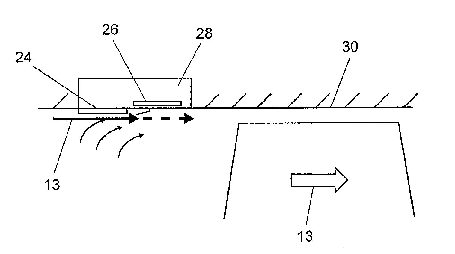
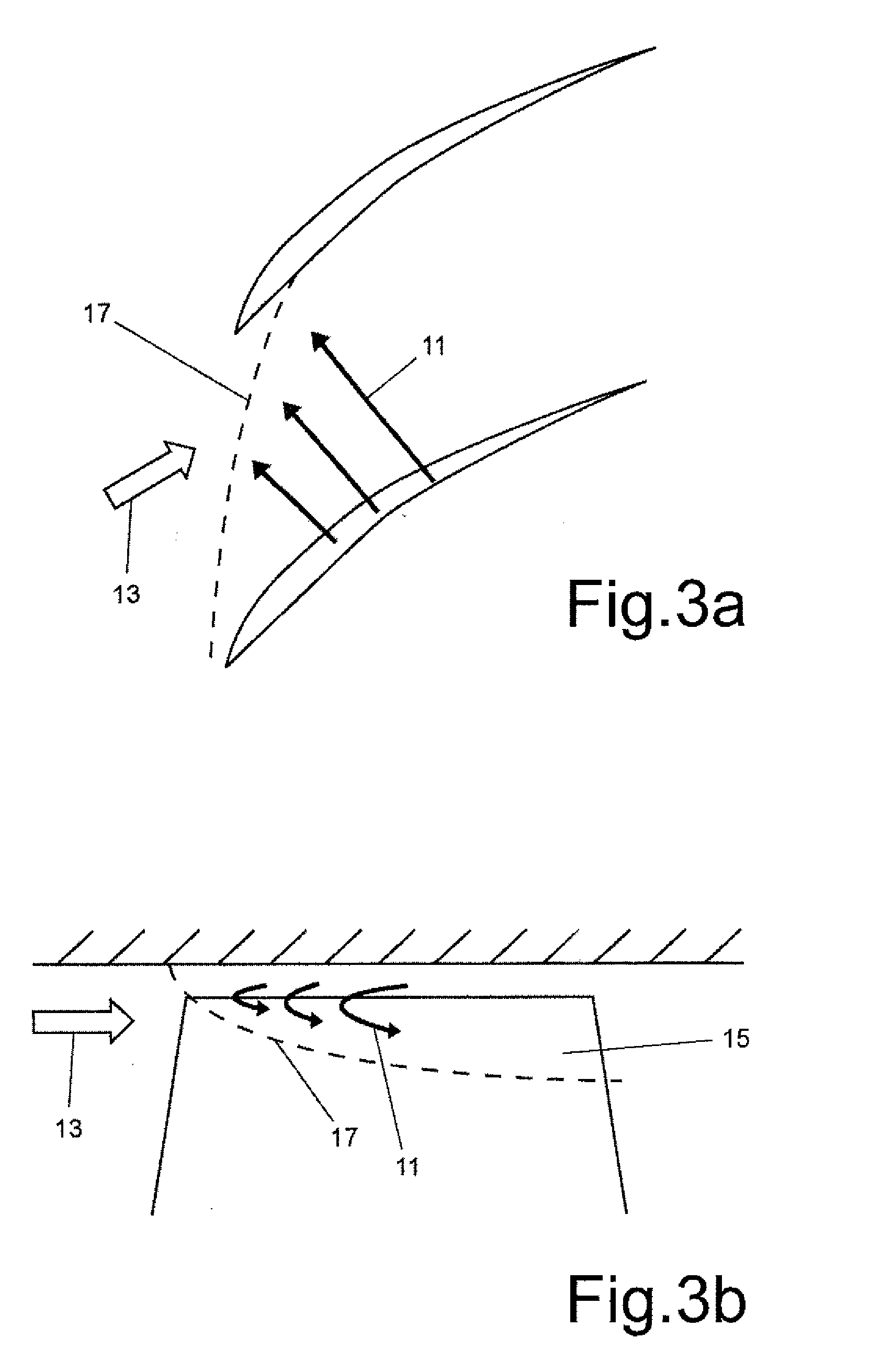
[0005]In accordance with another aspect, there is a method provided for suppressing rotating stall inception of a compressor, the compressor including a casing having an inner surface surrounding a rotor assembly, the rotor assembly having a plurality of circumferentially spaced radially outwardly extending rotor blades, each blade having leading and trailing edges and a tip, the method comprising actuating at least one plasma actuator disposed circumferentially around the casing near the blade tips of the rotor assembly to induce axial flow acceleration within a tip clearance gap region of the rotor assembly.
[0006]In accordance with a further aspect, there is a method for suppressing rotating stall inception of a compressor, the compressor including a casing having an inner surface surrounding a rotor assembly, the rotor assembly having a plurality of circumferentially spaced radially outwardly extending rotor blades, each blade having leading and trailing edges and a tip, the method comprising actuating independent adjacent plasma actuator sections around the casing near the blade tips of the rotor assembly to induce circumferentially varying axial flow acceleration within a tip clearance gap region of the rotor assembly, thereby resulting in a circumferential perturbation in pressure rise around the compressor.

Problems solved by technology

Engine surge is a major limiting factor in the operating envelope of aircraft gas turbine engines and is a concern in every new engine design.
It is characterized by the asymmetric flow oscillations across the entire engine that lead to a sudden drop in engine power and engine damage the severity of which depends on the strength of the surge.
Surge is a system instability associated with the interaction of the compressor with the combustor and turbine and is usually triggered by rotating stall.
Rotating stall is a well known compressor aerodynamic instability that occurs as the mass flow through the compressor is decreased at a certain speed.
It is characterized by the formation of a cell of axial velocity deficiency that rotates at a fraction of the compressor rotation speed and it usually results in a drop in compressor pressure rise.
A common practice of incorporating a safety margin against rotating stall, such as casing treatment or active control using moveable inlet guide vanes, often prevents the compressor from operating at peak efficiency and peak pressure ratio.
In another approach, micro injectors can be used to inject low mass flow jets into the compressors of gas turbine engines, however, the risk clogging and mechanical complexity are serious obstacles to practical implementation.

Method used


Image

  • Apparatus and method for controlling a compressor
  • Apparatus and method for controlling a compressor
  • Apparatus and method for controlling a compressor

Examples


Embodiment Construction

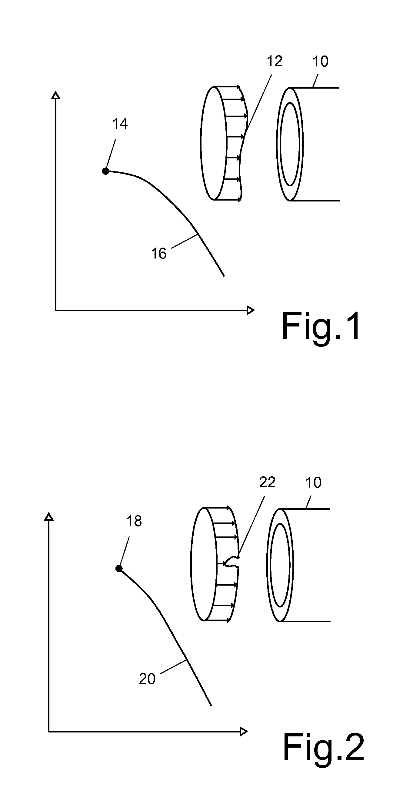
[0040]In FIGS. 1 and 2, two routes to rotating stall have been identified in an axial compressor 10: a long length-scale (modal) and short length-scale (spike) stall inception. Modal stall inception as illustrated in FIG. 1, is characterized by a long length scale (modal) disturbance 12 of the axial mass flow velocity Vx. It is characterized by the evolution in tens of rotor revolutions of a small full-span disturbance of circumferential wavelength on the order of the annulus into a full rotating stall cell and has been shown to occur at, or slightly beyond, the zero-slope peak 14 of the stagnation-to-static pressure rise characteristics (speedline 16) of the compressor 10. It has been understood and successfully modeled. The associated physics can essentially be described as a growth of disturbances in the compression system as the damping goes from positive (negative speedline slope) to negative (positive speedline slope). The relatively slow growth rate and initial low amplitude ...


PUM


Abstract

A compressor comprises a casing having an inner surface surrounding a rotor assembly, the rotor assembly having a plurality of circumferentially spaced radially outwardly extending rotor blades, each blade having leading and trailing edges and a tip, the compressor further comprising at least one plasma actuator for suppressing rotating stall inception of the compressor, the at least one plasma actuator being mounted adjacent to the blade tips.

Description

CROSS-REFERENCE TO RELATED APPLICATIONS[0001]This application claims the benefit of priority from U.S. Provisional Patent Application No. 61 / 034,839 entitled APPARATUS AND METHOD FOR CONTROLLING A COMPRESSOR filed on Mar. 7, 2008 which is incorporated herein by reference.TECHNICAL FIELD[0002]The technique described below generally relates to an apparatus and method for controlling a compressor of a gas turbine engine.BACKGROUND OF THE ART[0003]Engine surge is a major limiting factor in the operating envelope of aircraft gas turbine engines and is a concern in every new engine design. It can occur at critical operating regimes such as take-off, manoeuvres and engine acceleration. It is characterized by the asymmetric flow oscillations across the entire engine that lead to a sudden drop in engine power and engine damage the severity of which depends on the strength of the surge. Surge is a system instability associated with the interaction of the compressor with the combustor and turb...

Claims


Application Information

Patent Timeline
Patent Type & Authority Applications(United States)
IPC IPC(8): F01D11/14
CPCF01D11/20F04D27/02F05D2270/172F05D2270/102F04D29/687F05D2270/1022F05D2270/1024F04D29/522F05D2270/101
Inventor VO, HUU DUC
Owner PRATT & WHITNEY CANADA CORP
Why Eureka
Eureka Blog
Learn More