Microfluidic microarray assemblies and methods of manufacturing and using

a microfluidic microarray and assembly technology, applied in the field of manufacturing and using of microarray devices, can solve the problems of inability to use cdna, high cost of photolithographic synthesis methods, and inability to achieve cdna synthesis,

Inactive Publication Date: 2010-02-18
SIMON FRASER UNIVERSITY
View PDF8 Cites 21 Cited by
  • Summary
  • Abstract
  • Description
  • Claims
  • Application Information

AI Technical Summary

Benefits of technology

[0010]In one embodiment, the at least one first reagent may comprise a plurality of separate probes each distributed to selected test position(s) of the microarray in the first predetermined reagent pattern and the at least one second reagent may comprise a plurality of test samples each distributed to selected test position(s) of the microarray in the second predetermined reagent pattern. Positive or negative reactions between the probes (or other first reagent) and test samples (or other second reagent) may then be detected at the microarray test positions. For example, hybridization between selected nucleic acid probes and selected nucleic acid samples may be detected at particular test positions. In addition to nucleic acids and oligonucleotides, the first and second reagents may be selected from the group consisting of proteins, peptides, peptide-nucleic acids, oligosaccharides, antigens, immunoglobulins, cells, organelles, cell fragments, small molecules and chimeric molecules.
[0011]Various means may be provided for causing the first and second reagents to flow through the respective first and second microfluidic channels. In one particular embodiment, the test chip and the first and second channel plates are centrosymmetrical, for example circular. Subassemblies comprising the chip and one or more plates may be conveniently loaded into a spinning apparatus to generate centrifugal forces sufficient to cause fluid flow through the microfluidic channels.

Problems solved by technology

Such microarrays are typically formed either by on-chip photolithographic synthesis of oligonucleotides1 or by on-chip spotting of synthesized oligonucleotides.2 Both approaches have significant limitations.
The photolithographic synthesis method is expensive, limited to 50-mer oligonucleotide synthesis, and cannot be used for cDNA.
The spotting method uses expensive robots and pins, and wastes the oligonucleotide samples unless many microarray slides are prepared during one spotting procedure.
Moreover, microarray slides usually require large volumes of sample (e.g. 200 μL).
In some cases the spotting method has been performed on chips containing microfluidic channels.3, 4, 5, 6, 7 While spotting oligonucleotides into a microfluidic channel may reduce the required sample volume, the density of the resultant microarray is limited by the space required on the chip required to accommodate complicated liquid handling interfaces, such as microtubes, micropumps electrical contacts and the like.
Heretofore high density microarrays have not been successfully achieved using microfluidic techniques.
However, this approach has thus far not been employed to generate high density arrays (i.e. greater than about 16×16 channels).12 This is likely due to the difficulty in reliably flowing reagent fluid through large numbers of microchannels using conventional fluid delivery techniques, such as electrical current or pressure pumping.
For example, it is technically difficult and cumbersome to couple miniature electrical connections or pump conduits to large numbers of microchannels without causing fluid leakage or other undesirable chip failures.

Method used


Image

  • Microfluidic microarray assemblies and methods of manufacturing and using
  • Microfluidic microarray assemblies and methods of manufacturing and using
  • Microfluidic microarray assemblies and methods of manufacturing and using

Examples


example 1

DNA Hydridization

1.1 The Channel Plates for the Creation of a 96*96 Hybridization Microarray

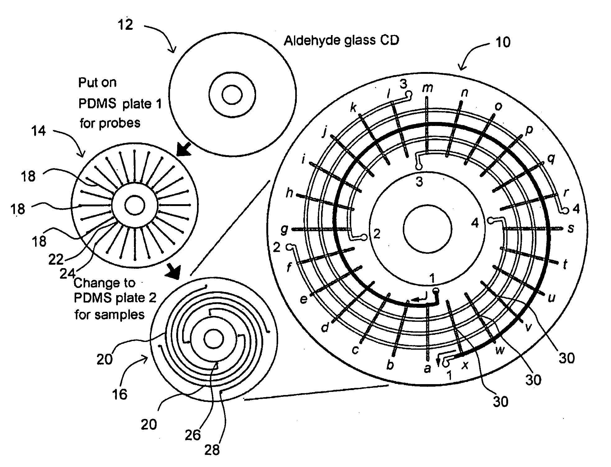
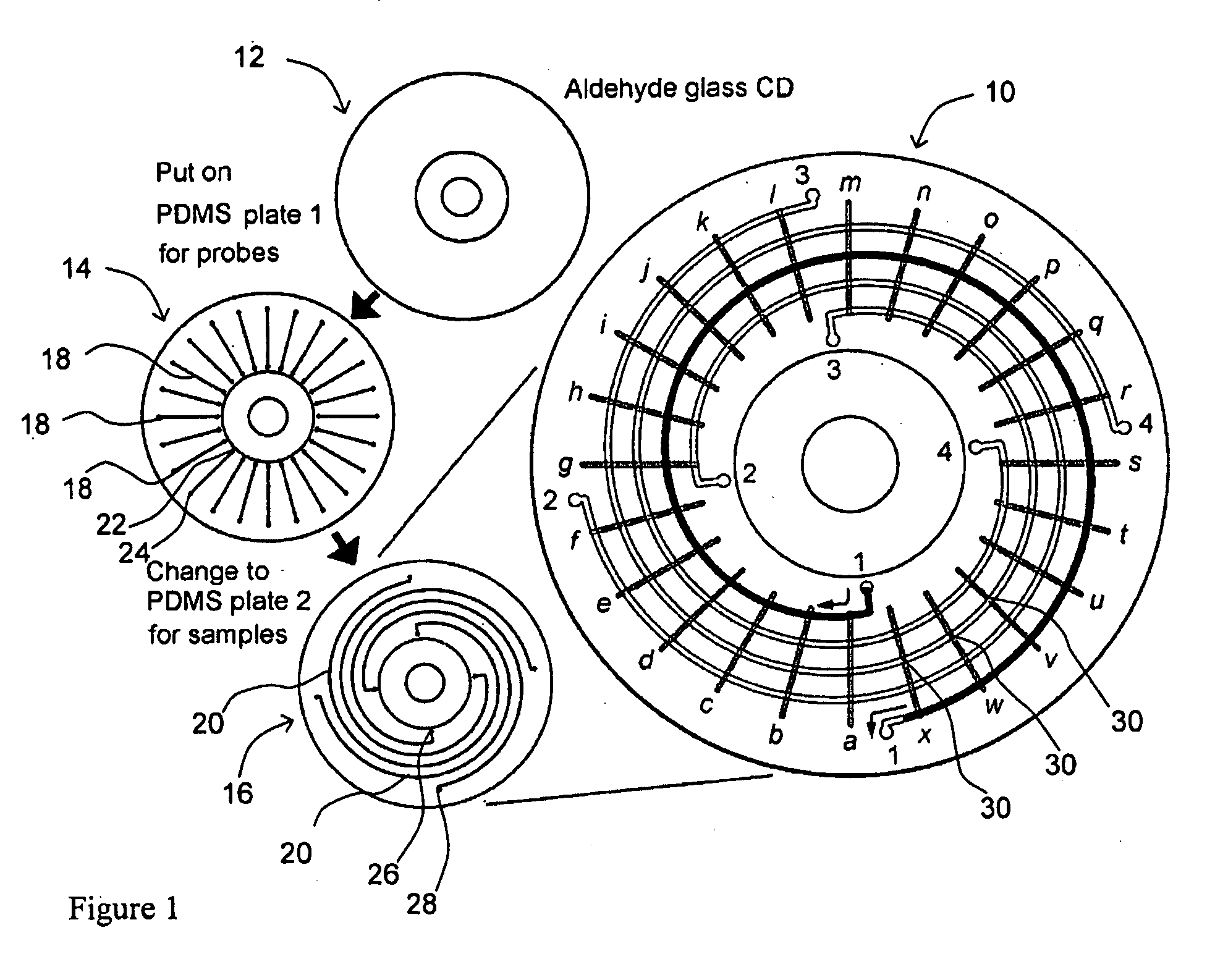
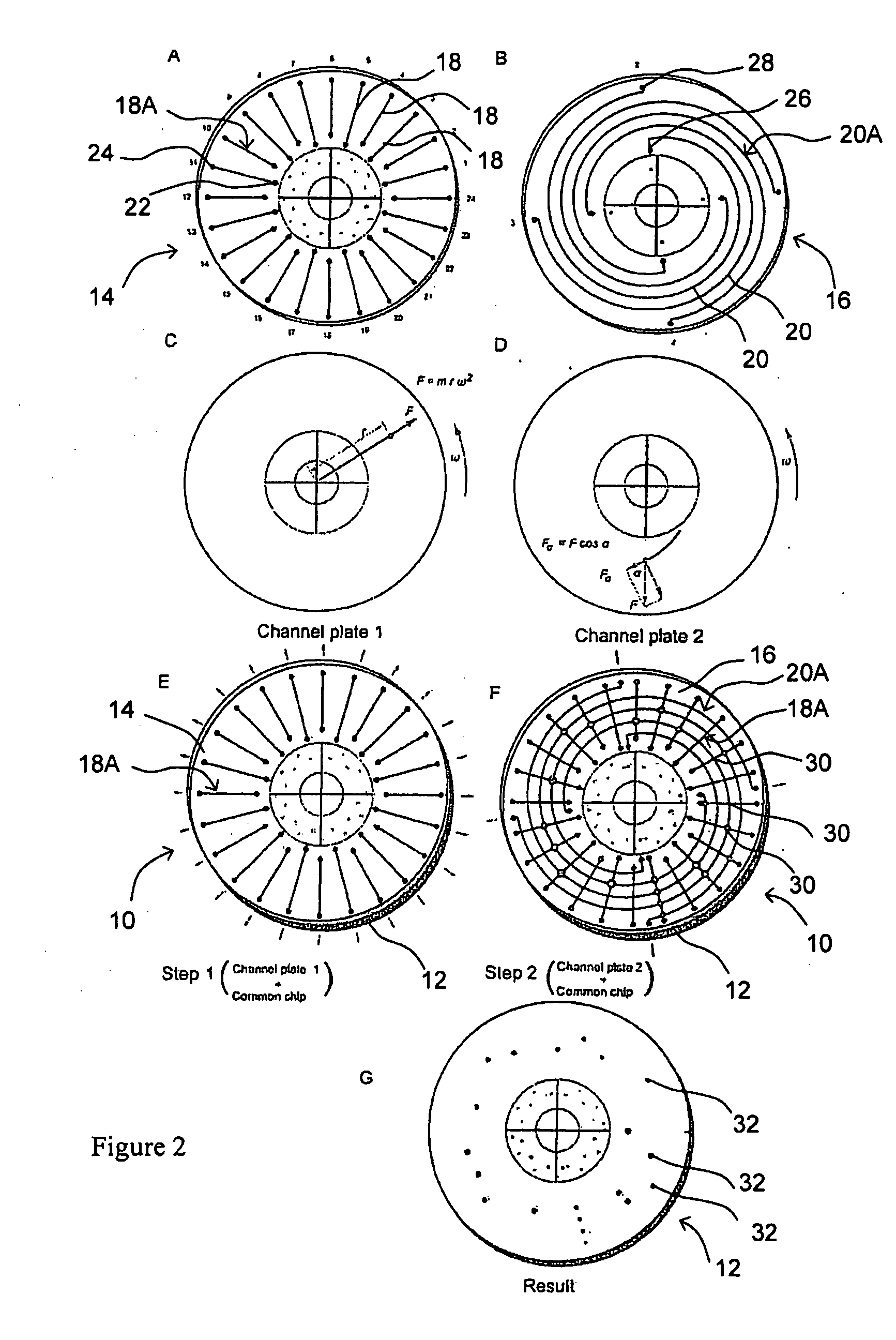
[0092]FIG. 6 shows the design of first and second channel plates 14, 16 in one embodiment of MMA 10. In FIG. 6A, first channel plate 14 has 96 microfluidic channels 18 for DNA probes arranged in a radial pattern. The left inset shows the molding master design of 5 microfluidic channels arranged in a radial pattern and the staggered, alternating positions of inlet reservoirs 22. The right inset shows the appearance of 5 PDMS microfluidic channels 18 formed from the molding master. In FIG. 6B, second channel plate 16 has 96 microfluidic channels 20 for samples arranged in a spiral pattern. The left inset shows the molding master design of the microfluidic channels arranged in a spiral pattern and the staggered, alternating positions of inlet reservoirs 26. The right inset shows the actual appearance of PDMS microfluidic channels 20 formed from the molding master. The size of the plate is 92 mm ...

example 2

Fluid Flow Velocity in the Spiral Microfluidic Channels

[0111]Liquid was successfully filled into spiral microfluidic channels during spinning or rotation of MMA 10. The result is shown in FIG. 13 in which 4 spiral microfluidic channels were filled with solutions containing blue food dye (Scott-Bathgate, Vancouver, BC). In one spiral microfluidic channel, the solution flowed from inlet reservoir A to outlet, reservoir C, see inset. In another spiral microfluidic channel, the solution flowed from inlet reservoir B to outlet reservoir D, see inset. The microfluidic channels were illuminated by a stroboscope light (Monarch, Nova-Strobe DA Plus 115) at the same frequency as the rotation speed. Using the stroboscope light, the movement of the fluid in the microfluidic channels can be seen flowing even though the chip is spun at high speed.

[0112]To study the fluid velocity in the spiral microfluidic channels, the positions of the advancing liquid front meniscus during filling of the spiral...

example 3

Cellomics Studies Using the MMA

[0127]Cell-based assays can also be conducted using MMA 10. The assays may be carried out using a batch of cells or single cells. The National Cancer Institute (NCI) has identified a total of 60 cancer cell lines, (NCI-60), which can be exposed to thousands of compounds for drug discovery.51 These cell lines are related to specific cancers: Lung (e.g. A549), Colon (e.g. HT29), Breast (e.g. estrogen-sensitive MCF7 and estrogen-insensitive MDA-MB-231), Ovarian, Leukemia (e.g. Jurkat), Renal, Melanoma, Prostate and Central Nervous System.

[0128]In these experiments, test chip 12 is arrayed with cells which are exposed to various drugs at different concentrations. For instance, 60 cells lines can be constructed as a cell microarray on a glass surface test chip 12 and hundreds of chemicals can be exposed to the cells at one time under the same flow and media conditions. For proof of concept, the 4 above cell lines, which are of biosafety level 1, are selecte...


PUM

PropertyMeasurementUnit
volumesaaaaaaaaaa
volumesaaaaaaaaaa
volumesaaaaaaaaaa

Abstract

Microarray devices fabricated using microfluidic reagent distribution techniques are provided. As described herein, the invention encompasses microfluidic microarray assemblies (MMA) and subassemblies and methods for their manufacture and use. In one embodiment first and second channel plates are provided which may be sealed to a test chip in consecutive steps. Each channel plate includes microfluidic channels configured in a predetermined reagent distribution pattern. For example, the first channel plate may have a radial (linear) reagent distribution pattern and the second channel plate may have a spiral (curved) reagent distribution pattern, or vice versa. In one embodiment the first channel plate is connected to the test chip and at least one first reagent is distributed on the test chip in a first predetermined reagent pattern. The first reagent is then immobilized on the test chip. Next, the first channel plate is removed, the second channel plate is connected to the test chip and at least one second reagent is distributed on the test chip in a second predetermined reagent pattern. The first and second reagent patterns intersect to define a plurality of microarray test positions on the test chip. In one embodiment, the first reagent may comprise a plurality of separate probes each distributed to selected test position(s) of the microarray and the second reagent may comprise a plurality of test samples each distributed to selected test position(s) of the microarray. Positive or negative reactions between the probes (or other first reagent) and test samples (or other second reagent) may then be detected at the microarray test positions. For example, hybridization between selected nucleic acid probes and selected nucleic acid samples may be detected at particular test positions. The invention thus provides an efficient means to fabricate high density multi-probe, multi-sample microarrays. Preferably the test chips and channel plates are circular and centrifugal force is used to achieve fluid flow through the microfluidic channels, such as by rotating the MMA in a disc spinner.

Description

RELATED APPLICATION[0001]This application claims the benefit of the filing date of U.S. provisional patent application No. 60 / 634,598 filed 10 Dec. 2004 which is hereby incorporated by reference.FIELD OF THE INVENTION[0002]This application relates to the manufacture and use of microarray devices using microfluidic reagent distribution techniques.BACKGROUND[0003]DNA microarray chips are well known in the prior art. Such microarrays are typically formed either by on-chip photolithographic synthesis of oligonucleotides1 or by on-chip spotting of synthesized oligonucleotides.2 Both approaches have significant limitations. The photolithographic synthesis method is expensive, limited to 50-mer oligonucleotide synthesis, and cannot be used for cDNA. The spotting method uses expensive robots and pins, and wastes the oligonucleotide samples unless many microarray slides are prepared during one spotting procedure. In both cases, each microarray slide created can be used with only one sample. ...

Claims


Application Information

Patent Timeline
Patent Type & Authority Applications(United States)
IPC IPC(8): C40B30/04C40B40/00C40B40/06C40B40/10C40B40/02C40B40/04C40B50/14
CPCB01J19/0046Y10T436/11B01J2219/00536B01J2219/00585B01J2219/00596B01J2219/00605B01J2219/00612B01J2219/00621B01J2219/00626B01J2219/0063B01J2219/00637B01J2219/00644B01J2219/00659B01J2219/00675B01J2219/00722B01J2219/00725B01J2219/00731B01J2219/0074B01J2219/00743B01L3/0293B01L3/502707B01L2200/025B01L2200/16B01L2300/0806B01L2300/0819B01L2300/0877B01L2400/0409B82Y30/00C40B80/00G01N33/54386G01N35/00069Y10T436/25Y10T436/2575Y10T436/118339Y10T436/117497B01J2219/00421
Inventor LI, PAUL CHI HANGPENG, XING YUEYU, HUA ZHONGPARAMESWAREN, MEENAKSHINATHANCHEN, HONGCHOU, WA LOK
Owner SIMON FRASER UNIVERSITY
Why Eureka
Try Eureka