Probe for scanning probe microscope

Inactive Publication Date: 2010-02-18
HITACHI CONSTR MASCH CO LTD +1
View PDF4 Cites 6 Cited by
  • Summary
  • Abstract
  • Description
  • Claims
  • Application Information

AI Technical Summary

Benefits of technology

[0012]As described above, it will be required to form the carbon nanotube tip with a cylindrical shape throughout including its extremity portion to improve reliability and reproducibility of the measured image.
[0013]An object of the present invention is to provide a probe having a tip whose length is adjusted and whose shape is kept cylindrically up to the extremity portion for ensuring the tip rigidity when using a nanotube, especially, a carbon nanotube as the tip and improving reliability and reproducibility of the measured image, and to provide its manufacturing method as well as a scanning probe microscope.
[0018]The probe having a nanotube tip whose length is accurately adjusted and shape is kept a cylindrical shape up to the extremity portion is capable of ensuring the maximum tip rigidity by obtaining a certain value of the length and diameter. Accordingly, the tip becomes capable of capturing accurately side surface shape and the side surface of the specimen with large roughness in comparing the conventional device and improving reproducibility of the measured image of every nanotube tip.

Problems solved by technology

When lengths and diameters of the carbon nanotube tips are different from each other, individual differences of them occur and the resultant measured image is not reproduced correctly.
If end of the carbon nanotube tip, however, is too sharpened or uneven, the maximum tip rigidity obtained by certain value of the length and diameter is not secured.
Furthermore, when the carbon nanotube tip having irregular diameter is worn out and the end potion diameter is changed, the image are also changed due to contact condition change with the specimen, and the resolution becomes difficult.
This change makes quantitative evaluation of the specimen shape based on the AFM image difficult.

Method used


Image

  • Probe for scanning probe microscope
  • Probe for scanning probe microscope
  • Probe for scanning probe microscope

Examples


embodiment 1

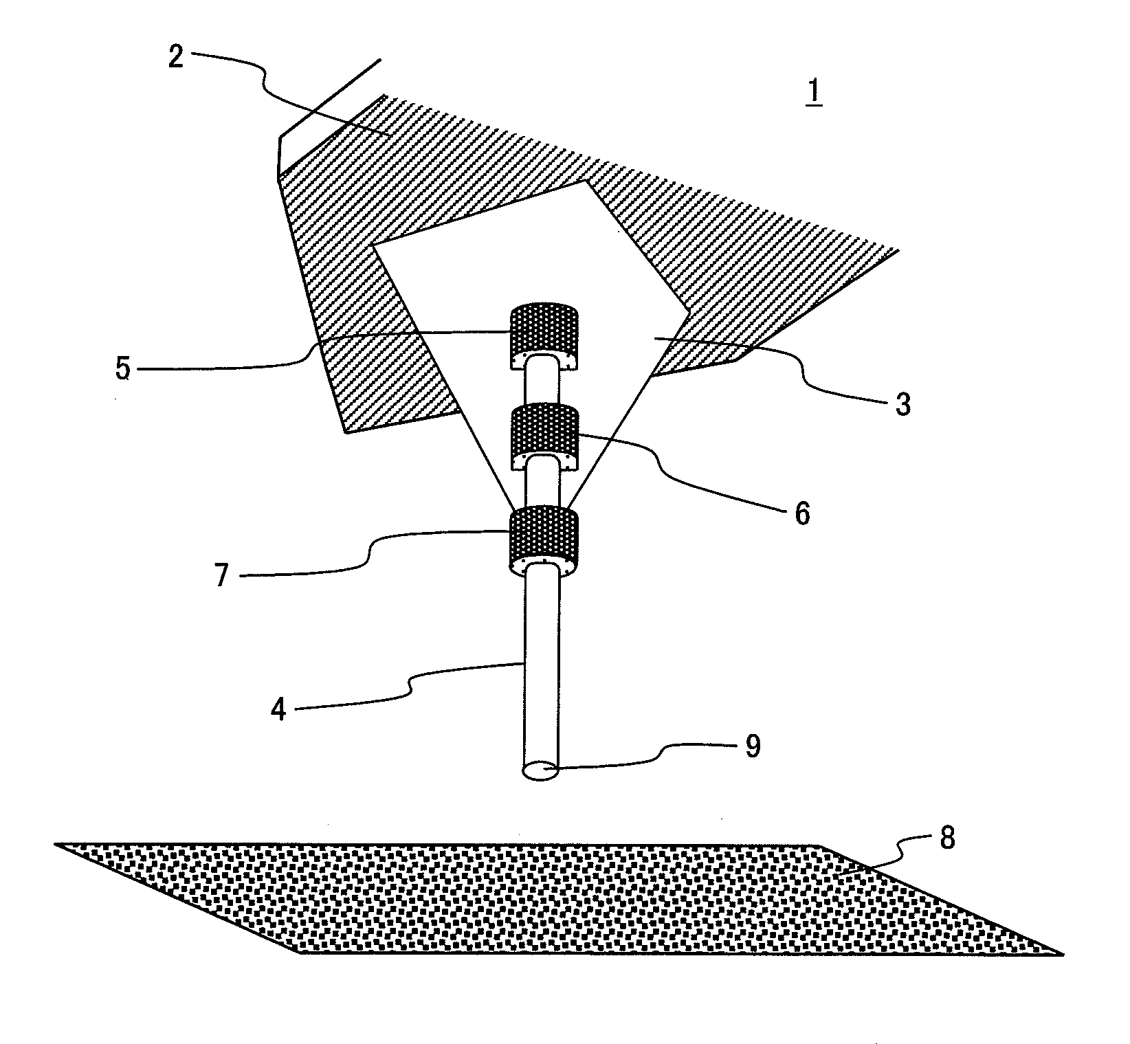
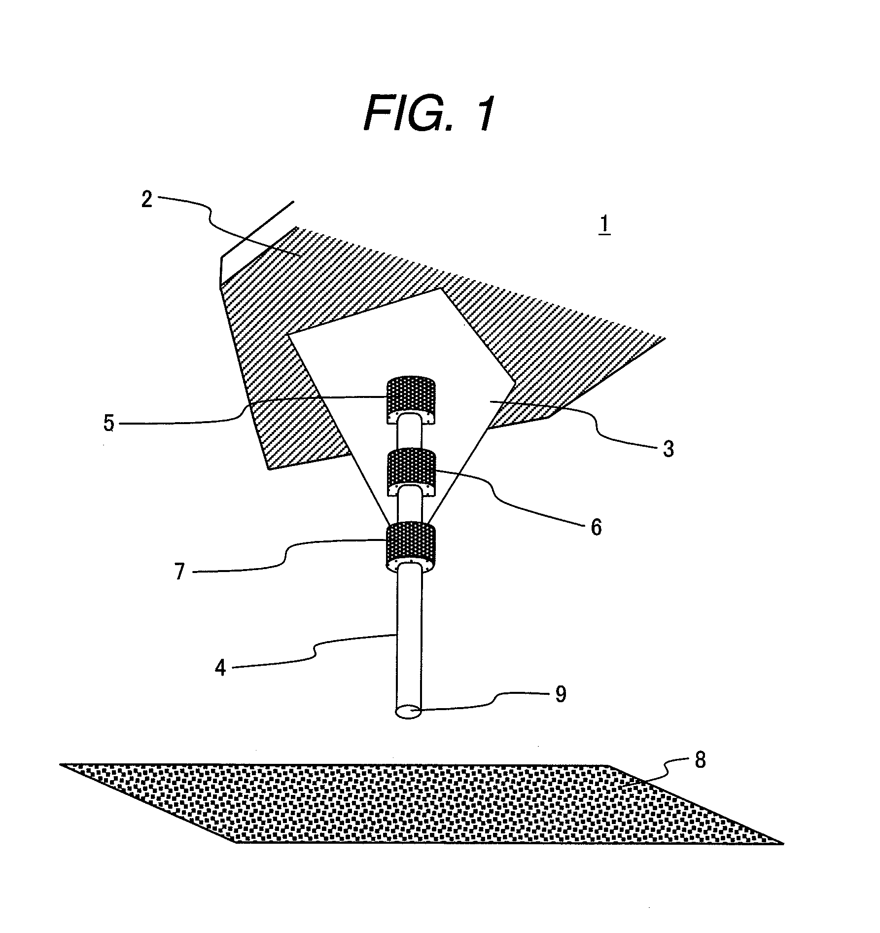
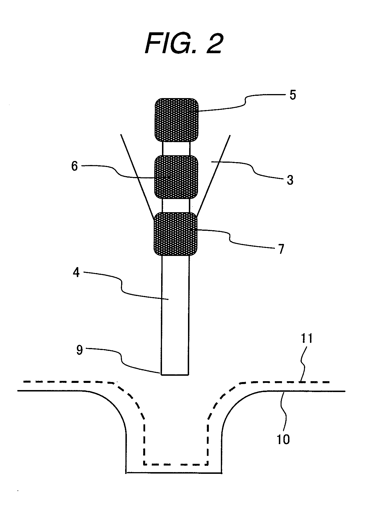
[0053]FIG. 6 shows the configuration of a scanning tip by an embodiment of this invention. In the scanning probe microscope of this embodiment, a cantilever 2 of a probe 1 is fixed to its base plate 12 as shown in a plan view and elevation view. The probe 1 comprises a carbon nanotube tip 4 having a flat end portion as the extremity, a tip holder 3 having a quadrangular pyramid shape for fixing the tip 4, and the cantilever 2 fixing the carbon nanotube tip 4. The carbon nanotube tip 4 is fixed to a ridge line of the tip holder 3 formed in the quadrangular pyramid shape at three portions, that is, a forward side joint 7, an intermediate joint 6 and a back side joint 5. An aluminum coating 13 is put on a rear surface of the cantilever 2.

[0054]FIG. 1 shows a state that the carbon nanotube tip 4 of the probe 1 was arranged so as to be perpendicular to a specimen flat surface 8. The carbon nanotube tip 4 having uniformed diameter is fixed at first to the tip holder 3 at the back side joi...

embodiment 2

[0066]When cutting a part of the extremity portion side of the carbon nanotube tip by flowing a current by the capacitor discharge, the end surface portion becomes amorphous throughout the thickness of the carbon nanotube layer.

[0067]FIG. 3 shows a case of pressing the end portion of the carbon nanotube tip with a certain constant pressure to the flat surface of the specimen and scanning in a direction as shown by an arrow to wear out it. The aspect ratio of the carbon nanotube tip is adjusted by repeating cutting at several times by the capacitor discharge. For example, when being used in a contact mode, a carbon nanotube tip is not initially worn out and stable images are obtainable from beginning of scanning.

embodiment 3

[0068]FIG. 4 is a perspective view of the carbon nanotube tip by the other embodiment of this invention. This embodiment used a carbon nanotube having uniform diameter and a flat end portion selected from many carbon nanotubes as a tip. At first, the tip was fixed at the back side joint 5 and intermediate joint 6 and then an angle of the tip was adjusted so as to be perpendicular against the specimen flatness surface 8 in the measurement state, and fixed at the forward side joint 7.

[0069]The aspect ratio of the tip is obtained from the ratio of the length from the forward side joint 7 to the diameter of the nanotube. In this embodiment, the width of the forward side joint 7 was lengthened to adjust the aspect ratio. In addition, the end bonding portion 7 is formed by the metal layer surrounding the carbon nanotube so as to go round in the radial direction of the carbon nanotube by 360 degrees.


PUM


Abstract

In a tip having a carbon nanotube tip used to a scanning probe microscope, its length of the tip is adjusted in a several order of 10 nm and the tip maintains cylindrical shape up to the extremity portion.

Description

CLAIM OF PRIORITY [0001]This application claims priority from Japanese patent application serial No. 2007-283764, filed on Oct. 31, 2007, the content of which is hereby incorporated by reference into this application.BACKGROUND OF THE INVENTION [0002]The present invention relates to a probe having a tip formed from a nanotube, especially, a carbon nanotube, a manufacturing method for the tip, and a scanning probe microscope.[0003]A high aspect ratio fine structure has been proposed according to the recent finer design of semiconductors and then accuracy of nanometer order has been required in the measurement techniques. The present miniaturization of the semiconductors goes into 45 nm node and the measurement becomes more and more difficult. At present, a scanning electron beam microscope (SEM) is used for observing a section of a semiconductor. Observation by the SEM is conventionally executed after making cleavage of a specimen or working a specimen by a focused ion beam (FIB). Su...

Claims


Application Information

Patent Timeline
IPC IPC(8): G01B5/28G01Q70/12G01Q70/16
CPCB82Y15/00G01Q70/12B82Y35/00
Inventor HIROOKA, MOTOYUKIOKAI, MAKOTOMORIMOTO, TAKAFUMISEKINO, SATOSHITANAKA, HIROKITAKASHINA, MASATOUOZUMI, YUUKI
Owner HITACHI CONSTR MASCH CO LTD
Why Eureka
Try Eureka