System and method of cooling turbines

a cooling turbine and cooling system technology, applied in the field of maintenance of equipment, can solve the problems of extreme costs, much more substantial, and a substantial cooling period, and achieve the effects of reducing the cooling time, improving the cooling time, and reducing the temperature of the main steam

Inactive Publication Date: 2010-02-25
BAKER HUGHES INC
View PDF10 Cites 7 Cited by
  • Summary
  • Abstract
  • Description
  • Claims
  • Application Information

AI Technical Summary

Benefits of technology

[0013]The prior art offers two methods to improve the cooling time associated with large steam turbines. The primary method of reducing the cool down time is to force cool the turbine components prior to bringing the turbine off-line. This typically consists of reducing the main steam temperature just prior to removing the steam tu

Problems solved by technology

This cool down period can represent a substantial cost if the outage occurs at critical electrical power market conditions.
Th

Method used


Image

  • System and method of cooling turbines
  • System and method of cooling turbines
  • System and method of cooling turbines

Examples


Embodiment Construction

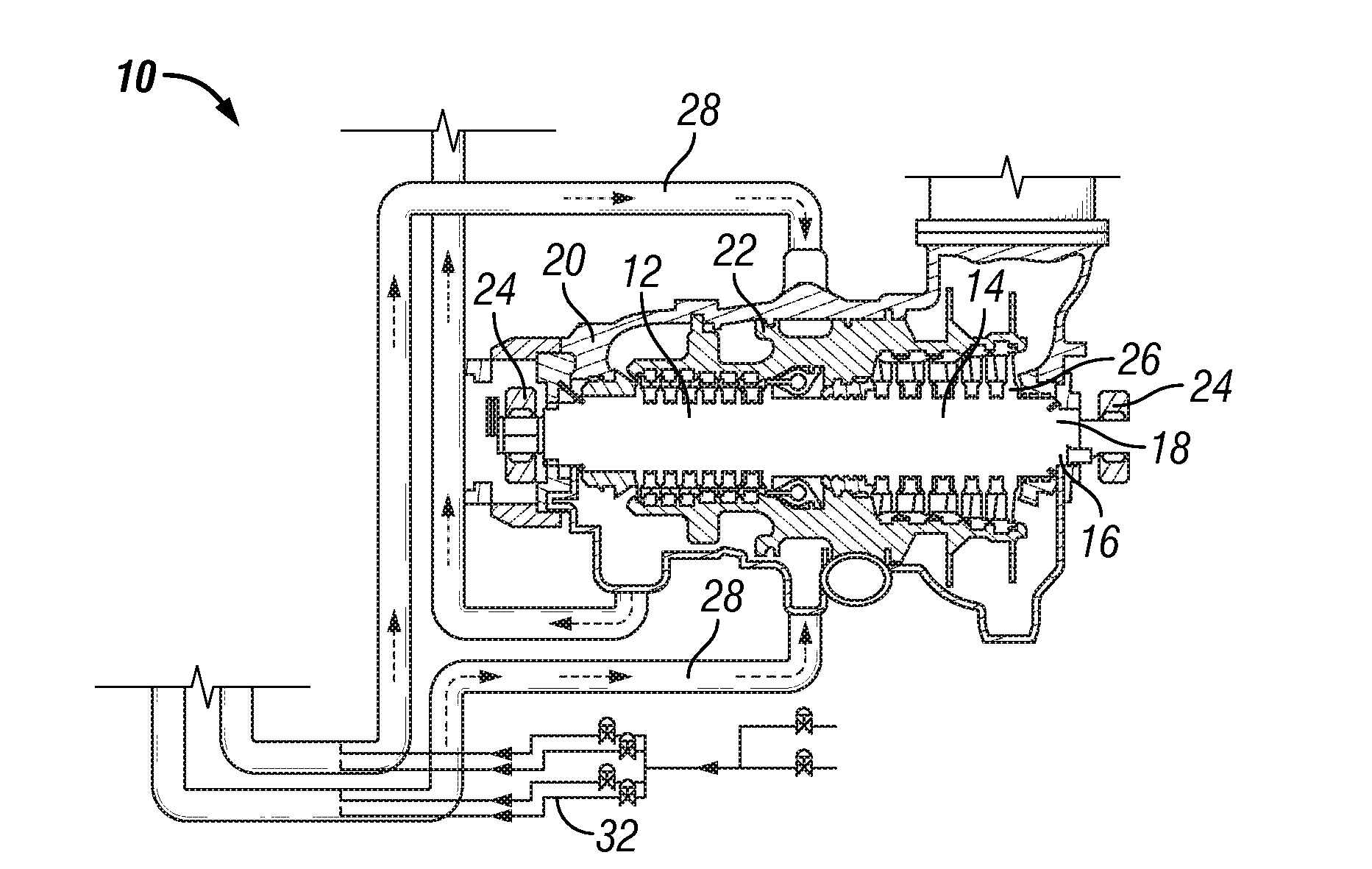
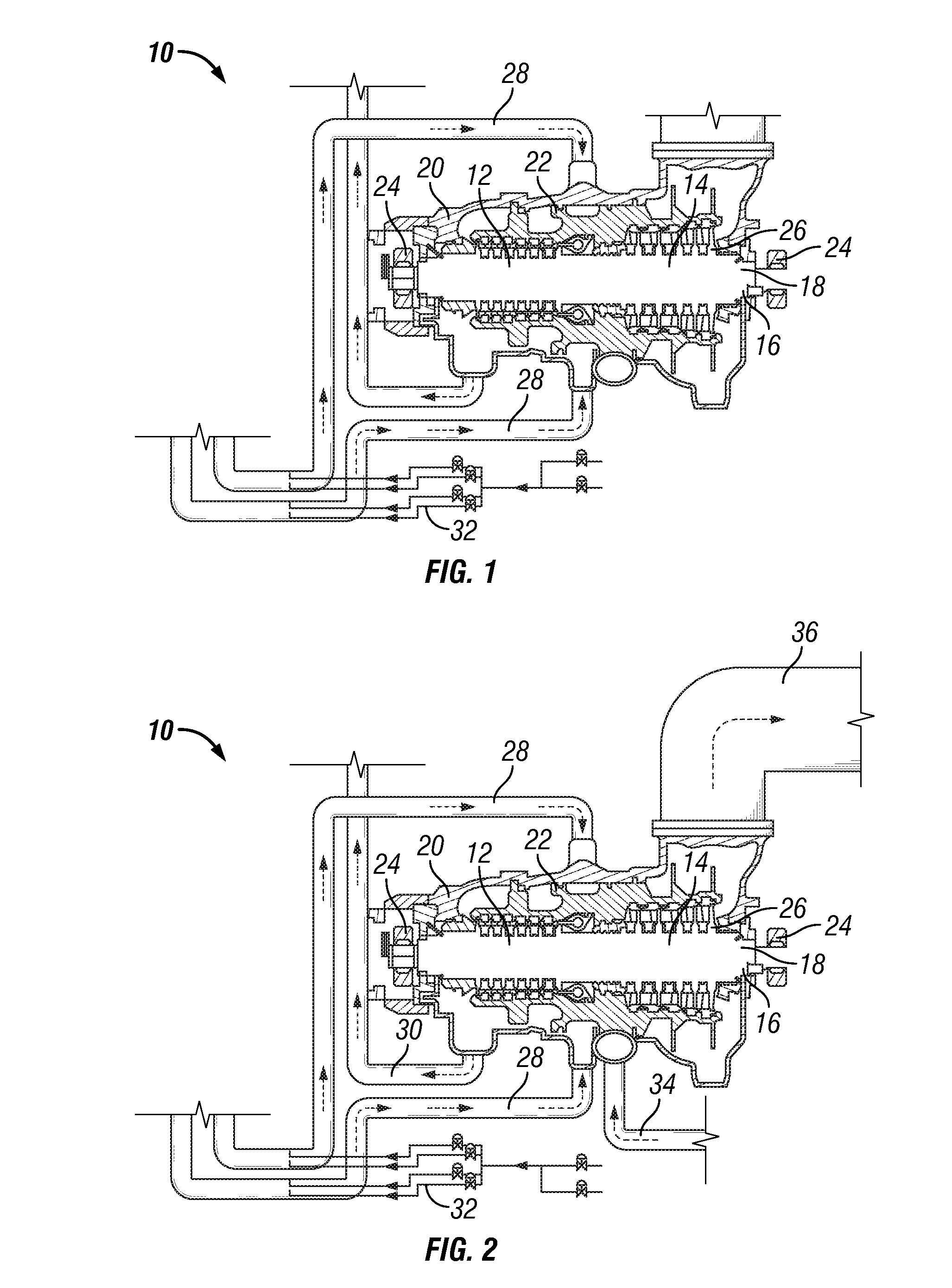
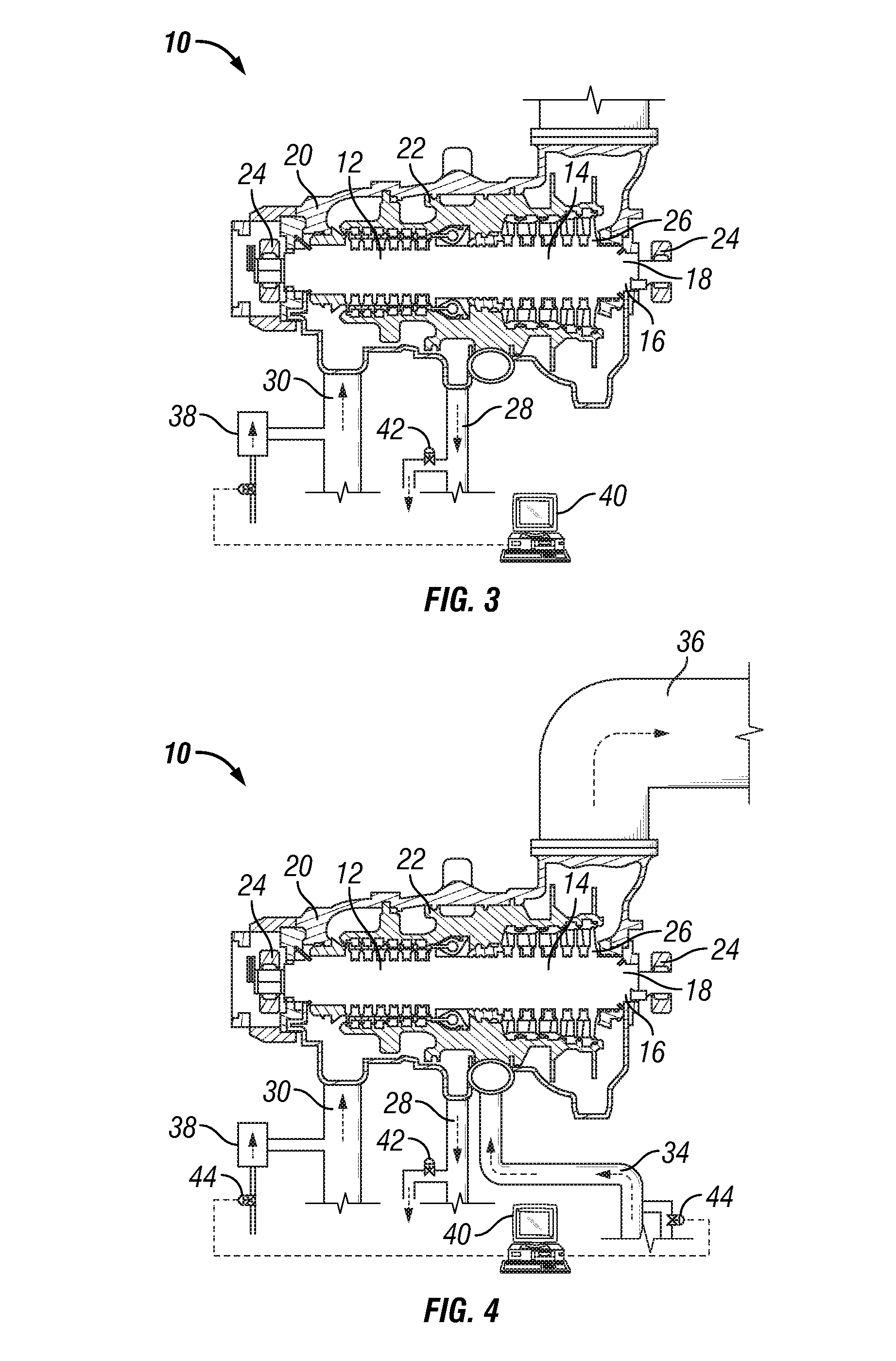
[0062]The present disclosure offers forced cooling of a flow of nitrogen such that a steam turbine may be cooled in a shorter period of time. In a most preferred embodiment, it is expected that a typical large fossil steam turbine unit between 200 and 850 megawatt (“MW”) may be cooled in less than about 48 hours, more preferably less than about 36 hours, most preferably about 24 hours. In fact, it is envisioned that a cool down could be accomplished in as little as about four to about 15 hours in a most preferred embodiment. The time required is dependent on the overall mass of the turbine and the nitrogen flows that can be obtained. The cooling time will be determined by the difference between the time of operation and the time at which the turbine has cooled down from the range of about 350° F. to about 700° F. to a predetermined temperature such as less than about 100° F. to about 200° F. It is expected that substantial differences between turbine sizes, manufactures and power pl...


PUM

PropertyMeasurementUnit
Temperatureaaaaaaaaaa

Abstract

A method of cooling a turbine having internal moving components to a predetermined temperature is disclosed. The method comprises taking the turbine offline. While the turbine is offline, nitrogen is flowed through the turbine until the turbine reaches the predetermined temperature while controlling the flow of nitrogen from at least one injection point to prevent damage to the moving components of the turbine by achieving uniform cooling of the internal moving components. Then the flow of nitrogen is stopped. A method and assembly for cleaning a turbine having a deposit formed on an internal surface of the turbine is also disclosed.

Description

RELATED APPLICATIONS[0001]The present application is a continuation-in-part of U.S. patent application Ser. No. 11 / 110,403, filed Apr. 20, 2005, which is a continuation of U.S. patent application Ser. No. 10 / 628,035, filed on Jul. 25, 2003, now issued as U.S. Pat. No. 6,898,935, both of which applications are incorporated herein by reference in their entirety.FIELD OF THE DISCLOSURE[0002]This disclosure relates to the field of maintenance of apparatus having moving internal components, namely in the power generation industry.BACKGROUND[0003]In the power industry, electricity is produced with a spinning turbine that is turned at high speeds to generate electricity. This turbine can be turned by water, by gas, or by high temperature steam. The steam turbine is driven by high temperature steam from a conventional boiler reactor or nuclear reactor at speeds averaging 1800 to 3600 rpm. Many of the modern stream turbines operate at temperature in excess of 1,000° F.[0004]Approximately 49 ...

Claims


Application Information

Patent Timeline
IPC IPC(8): F01K13/02F01D25/12F01K21/00
CPCF01D21/00F01D25/002B08B5/00F05D2260/232F02C7/18
Inventor BARBER, STEVEN J.
Owner BAKER HUGHES INC
Why Eureka
Try Eureka