Solar and thermal energy to electricity conversion

a technology of solar energy and electricity, applied in the safety of solar heat collectors, light and heating apparatuses, machines/engines, etc., can solve the problems of high manufacturing and material cost, high cost of manufacturer and material cost, and high cost of light sensitive material or thermal sensitive material, so as to reduce the gap, increase the gap, and increase the gap

Inactive Publication Date: 2010-02-25
PENG GANG GRANT
View PDF13 Cites 4 Cited by
  • Summary
  • Abstract
  • Description
  • Claims
  • Application Information

AI Technical Summary

Benefits of technology

[0015]The present invention provides a means of converting the solar energy directly into electricity at the grid voltage. The primary object of the present invention is to establish an apparatus and method to convert the solar energy to electricity directly by a different approach rather than by the existing technologies. The first embodiment coverts the solar energy collected by a parabolic trough to mechanical energy by elongating a metallic bar when heated. The elongated metallic bar will either increase the gap between two plates of a capacitor which results in more energy stored in the capacitor or decrease the gap which results in less energy stored in the capacitor. When the capacitor is connected to a circuit or a grid, the extra electric energy in the capacitor will be transferred out of the capacitor into the circuit or grid.

Problems solved by technology

But the manufactory and material cost are high.
However, the light sensitive material or the thermal sensitive material is more problematic for its stability, charge uniformity, and durability of the operation condition of the normal power grid.
The need for exotic material for the thermoelectric device makes it expensive and environmentally unfriendly.g) Changing the gap of a capacitor will generate electricity as well because it increases the system energy when the capacitance has reduced.
This adds costs to the solar energy application as well as lower the photo-electricity conversion efficiency.

Method used


Image

  • Solar and thermal energy to electricity conversion
  • Solar and thermal energy to electricity conversion
  • Solar and thermal energy to electricity conversion

Examples


first embodiment

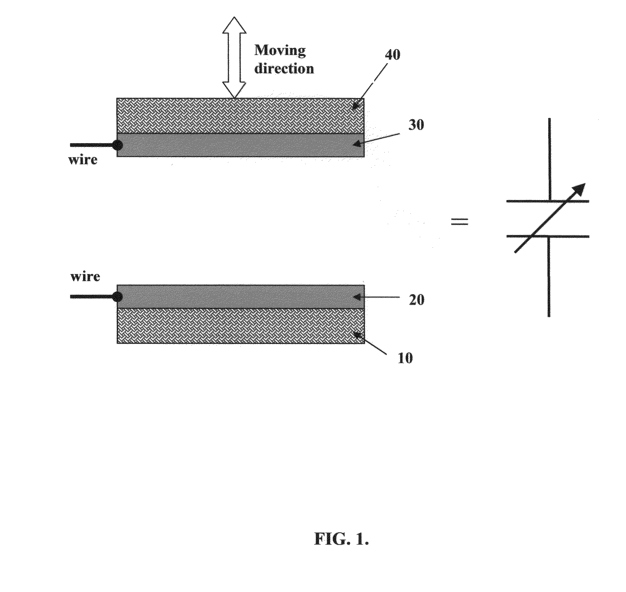
[0044]the present invention is illustrated in FIG. 1. which shows the apparatus of a parallel-plates-type of variable capacitor. The plates, 10 and 40, can be made of either metal or non metal materials. The films, 20 and 30, will be made of conductive material and they may be the same or different. When the gap between these plates change, the energy stored in its electric field change accordingly. The energy storage for this type of variable capacitor can be described as:

Uf=U0·(dfd0)(3)

where Uf and U0 are the final and initial energy stored in the capacitor respectively, and df and d0 are the final and initial gaps respectively. The capacitor is charged at its initial stage—gap, and then external work increases the gap, which results in higher energy stored in the capacitor. The larger the gap, the higher the energy stored in the capacitor because of weaker static interactions between the charges on the two plates.

second embodiment

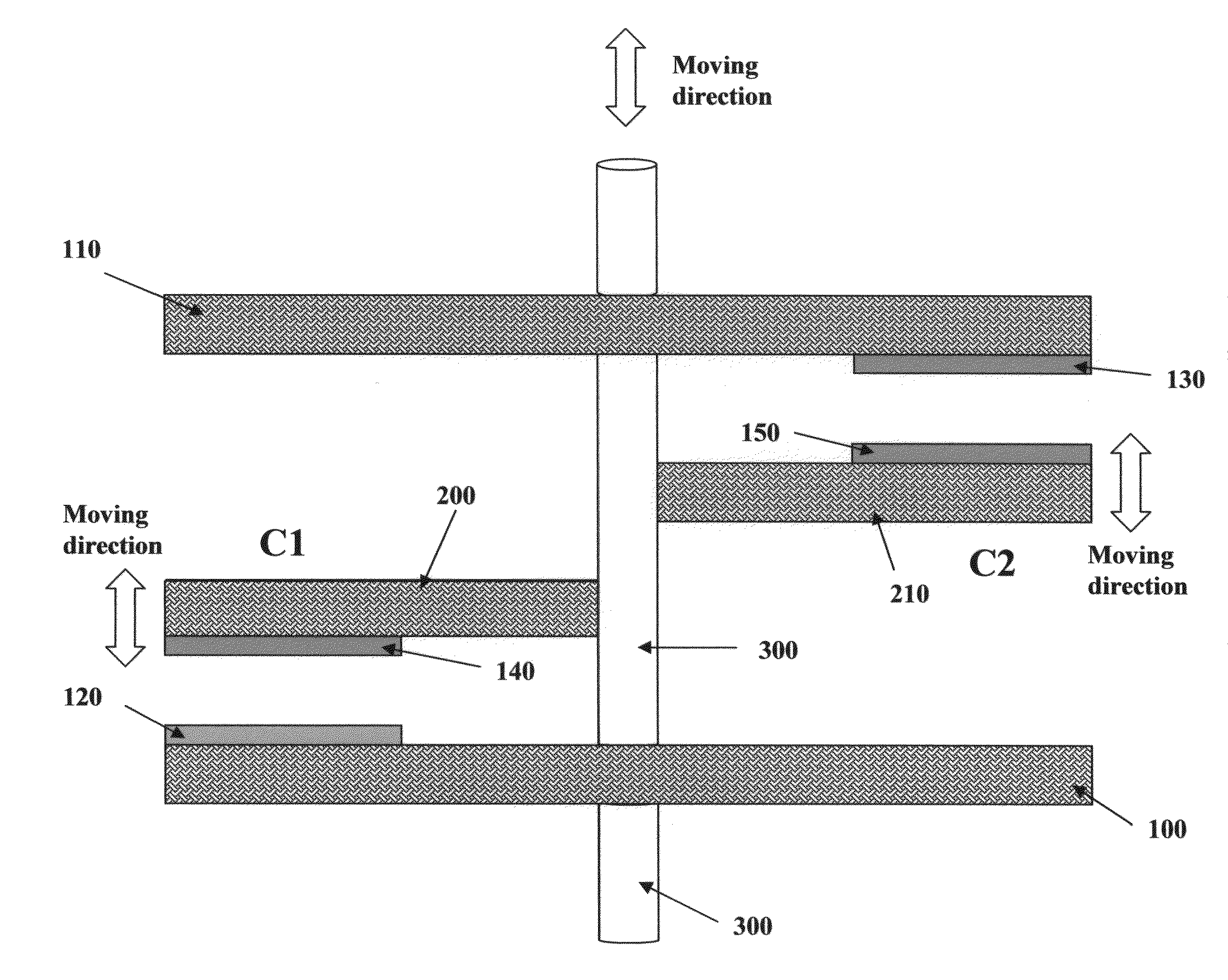
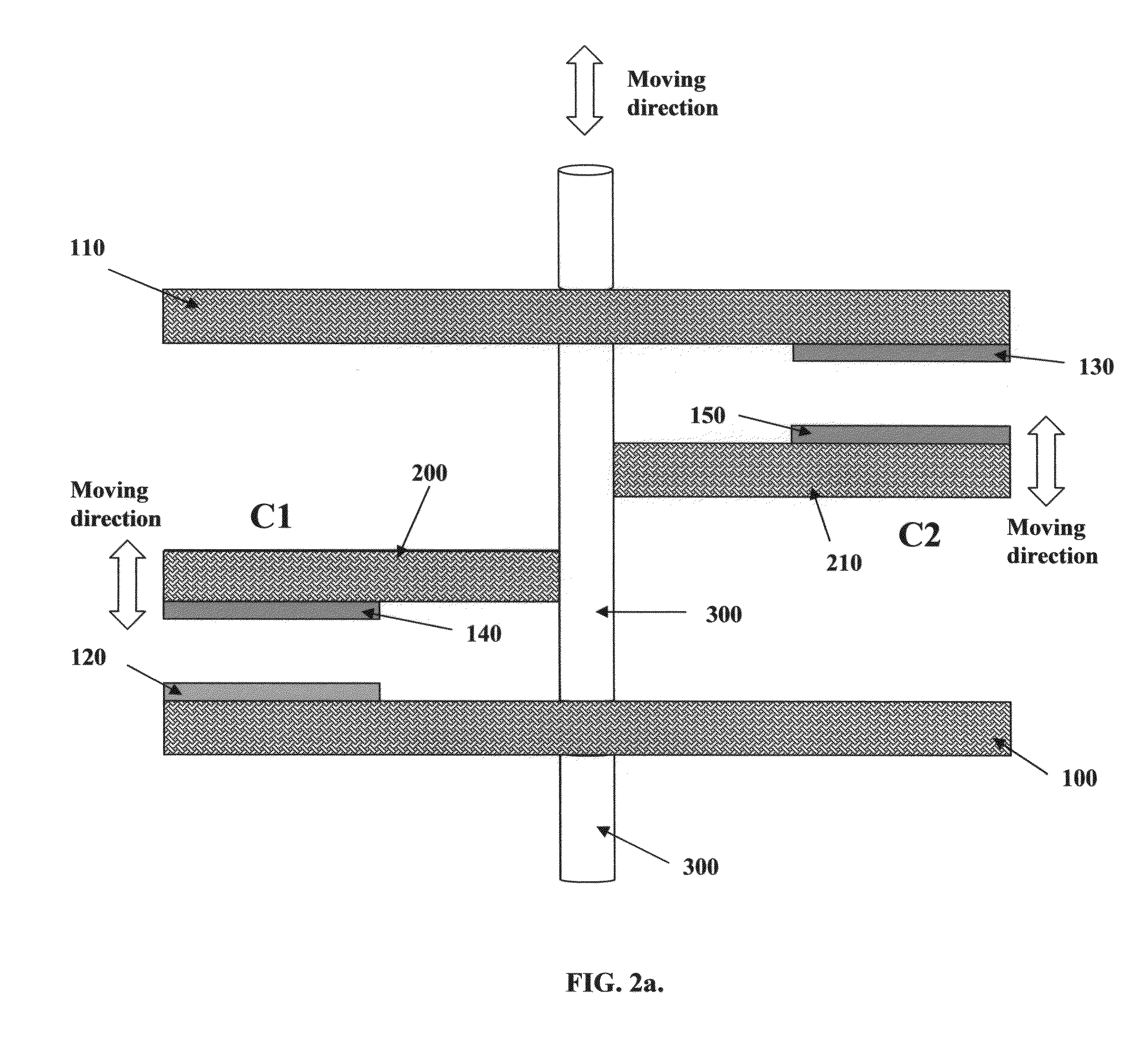
[0045]The second embodiment in the present invention is illustrated by FIG. 2a, which shows the apparatus having a pair of variable capacitors (parallel plates type), C1 and C2. The C1 and C2, each has a fixed plate, 100 and 110, and a moving plate, 200 and 210, respectively. These plates can be made of metal, semiconductor or insulator. They have aligned metallic films, 120, 130, 140, and 150, which may be different for the moving plate and fixed plate. The moving plates, 200 and 210, are attached to the fixture, 300, and therefore move along with the motion of 300. The circuit connected to both C1 and C2 are controlled with two independent switchers, S1 and S2, respectively. The variable capacitor operation can be illustrated by the following example. When the variable capacitor C1 is at its initial stage, it has the narrowest gap and the switch S1 closes, therefore a current starts to charge C1. Meanwhile, C2 has the widest gap and S2 is closed to transfer energy from C2 to the c...

third embodiment

[0046]the present invention can be discussed by referring to FIG. 3, which shows the apparatus of the solar energy conversion system. This conversion system uses solar energy and cooling media such as running water or cold air to move the plates of the pair of capacitors back forward. The solar energy is concentrated by a solar reflection trough, 600, which focuses the solar energy to the thermal collector, 500. The thermal collector 500 is fixed at one end by 520 and flexible at the other end with supporter 530. The fixtures 400 is fixed on the flexible end of the collector 500 and connected to the fixture 300. The variable plates, 200 and 210, are fixed on the fixture 300. The stationed plates 100 and 110 are fixed on the base support 240. When the thermal collector 500 has thermal motion—expansion or contraction, the fixtures 400, 300 and the variable plates 200 and 210 move along accordingly. The thermal collector 500 is made of a material with a large thermal expansion coeffici...


PUM


Abstract

The present invention discloses a new apparatus and method for converting solar energy or thermal energy to electricity, requiring simple design and production. The present invention will apply the work from the solar or thermal energy to the variable capacitors that convert into electric energy. The output energy from the present invention will be ready for grid connection.

Description

REFERENCES SITEDUS PATENT DOCUMENTS[0001]7,405,013Jul. 29, 2008Yang et al.429 / 137,340,898Mar. 11, 2008Miller. 60 / 641.86,898,450May 24, 2005Eden et al.505 / 2106,326,541Dec. 4, 2001Goheen.136 / 2535,644,184Jul. 1, 1997Kucherov.310 / 3064,425,540Jan. 10, 1984Olsen.322 / 2 A4,213,797Jul. 22, 1980Sher136 / 894,151,409Apr. 24, 1979O'Hare.250 / 2122,981,777Apr. 21, 1961Reynolds.BACKGROUND OF THE INVENTION[0002](1) Field of the Invention[0003]The present invention relates to the convertion of solar energy into electric energy, particularly to a conversion apparatus and method including a solar energy collector, a thermal (or from solar energy)-mechanical energy conversion, and a mechanical-electrical energy conversion.[0004](2) Prior Art[0005]There are following major technologies for utilizing solar energy:[0006]a) converting solar energy into electricity—the photovoltaic (PV). The photovoltaic is based on the principle of a photon generating a free electron and a hole in semiconductor material and o...

Claims


Application Information

Patent Timeline
Patent Type & Authority Applications(United States)
IPC IPC(8): H01L31/042
CPCF03G6/00F03G7/06F24J2/14F24J2/4636Y02E10/46H02N1/08Y02E10/45Y02E10/52H01G5/16F03G6/06F24S40/80F24S23/74Y02E10/40
Inventor PENG, GANG GRANT
Owner PENG GANG GRANT
Why Eureka
Try Eureka