Apparatus for Advancing a Wellbore Using High Power Laser Energy

Active Publication Date: 2010-02-25
FORO ENERGY
View PDF102 Cites 80 Cited by
  • Summary
  • Abstract
  • Description
  • Claims
  • Application Information

AI Technical Summary

Benefits of technology

[0017]It is desirable to develop systems and methods that provide for the delivery of high power laser energy to the bottom of a deep borehole to advance that borehole at a cost effect rate, and in particular, to be able to deliver such high power laser energy to drill through rock layer formations including granite, basalt, sandstone, dolomite, sand, salt, limestone, rhyolite, quartzite and shale rock at a cost effective r

Problems solved by technology

To date it is believed that no one has succeeded in developing and implementing these laser drilling theories to provide an apparatus, method or system that can advance a borehole through the earth using a laser, or perform perforations in a well using a laser.
Moreover, to date it is believed that no one has developed the parameters, and the equipment needed to meet those parameters, for the effective cutting and removal of rock and earth from the bottom of a borehole using a laser, nor has anyone developed the parameters and equipment need to meet those parameters for the effective perforation of a well using a laser.
In particular, it is believed that no one has developed parameters, equipments, or methods nor implemented the delivery of high power laser energy, i.e., in excess of 1 kW or more to advance a borehole within the earth.
The environment and great distances

Method used


Image

  • Apparatus for Advancing a Wellbore Using High Power Laser Energy
  • Apparatus for Advancing a Wellbore Using High Power Laser Energy
  • Apparatus for Advancing a Wellbore Using High Power Laser Energy

Examples


Embodiment Construction

Drillingtype / LaserDepthRock typepower down holeDrill 17½Surface -Sand andConventionalinch hole3000 ftshalemechanicaldrillingRun 13⅜Length 3000 ftinch casingDrill 12¼ inch3000 ft-8,000 ftbasalt40 kWhole(minimum)Run 9⅝ inchLength 8,000 ftcasingDrill 8½ inch8,000 ft-11,000 ftlimestoneConventionalholemechanicaldrillingRun 7 inchLength 11,000 ftcasingDrill 6¼ inch11,000 ft-14,000 ftSand stoneConventionalholemechanicaldrillingRun 5 inchLength 3000 ftliner

[0092]Drilling Plan Example 2

Drilling type / LaserDepthRock typepower down holeDrill 17½Surface - 500 ftSand andConventionalinch holeshalemechanicaldrillingRun 13⅜Length 500 ftcasingDrill 12¼ hole500 ft-4,000 ftgranite40 kW(minimum)Run 9⅝ inchLength 4,000 ftcasingDrill 8½ inch4,000 ft-11,000 ftbasalt20 kWhole(mimimum)Run 7 inchLength 11,000 ftcasingDrill 6¼ inch11,000 ft-14,000 ftSand stoneConventionalholemechanicaldrillingRun 5 inchLength 3000 ftliner

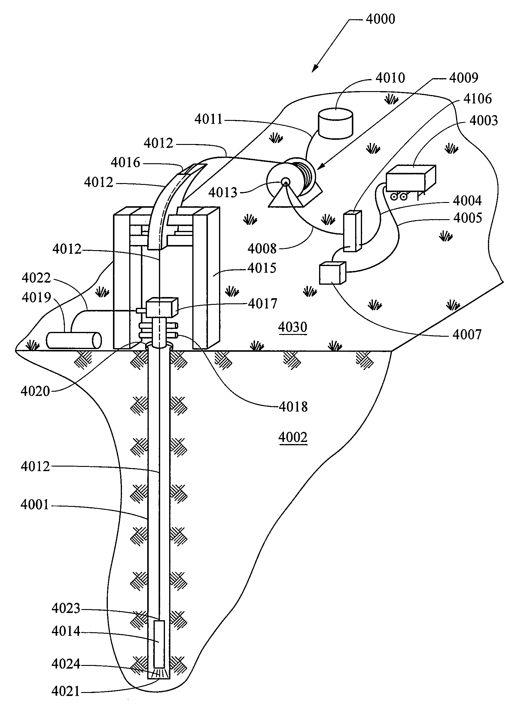
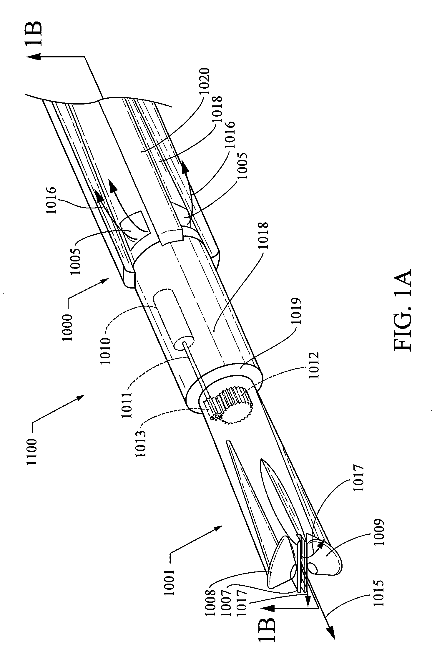
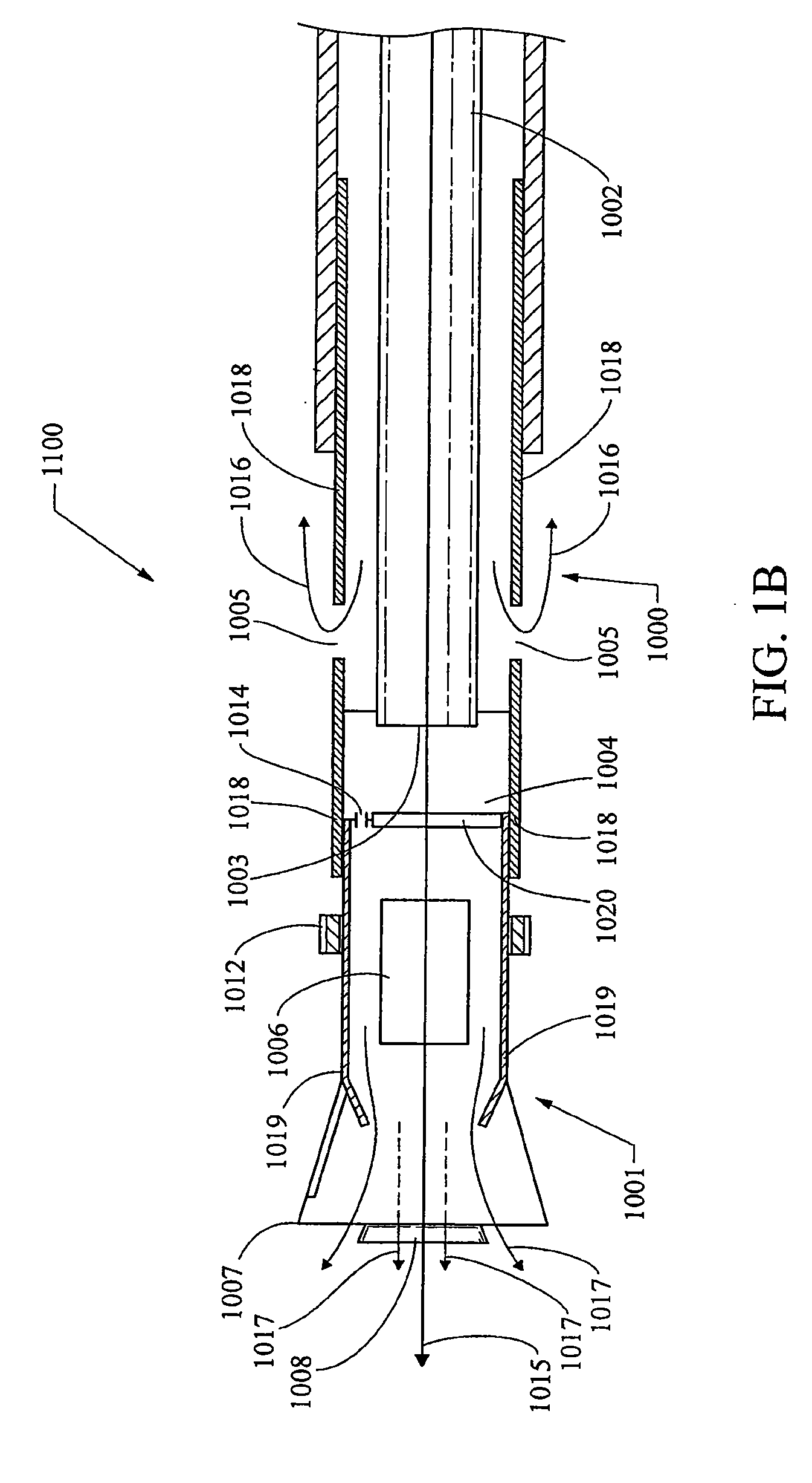
[0093]Thus, in general this system operates to create and / or advance a borehole by having ...


PUM


Abstract

There is provided a system, apparatus and methods for delivering high power laser energy to advance a borehole deep into the earth using laser energy. In particular, there is provided a laser bottom hole assembly (LBHA) for the delivery of such laser energy to the surfaces of a borehole, which assembly may have laser optics, a fluid path for debris removal and a mechanical means to remove earth.

Description

BACKGROUND OF THE INVENTION[0001]This application claims the benefit of priority of provisional applications: Ser. No. 61 / 090,384 filed Aug. 20, 2008, titled System and Methods for Borehole Drilling: Ser. No. 61 / 102,730 filed Oct. 3, 2008, titled Systems and Methods to Optically Pattern Rock to Chip Rock Formations; Ser. No. 61 / 106,472 filed Oct. 17, 2008, titled Transmission of High Optical Power Levels via Optical Fibers for Applications such as Rock Drilling and Power Transmission; and, Ser. No. 61 / 153,271 filed Feb. 17, 2009, title Method and Apparatus for an Armored High Power Optical Fiber for Providing Boreholes in the Earth, the disclosures of which are incorporated herein by reference.[0002]The present invention relates to methods, apparatus and systems for delivering high power laser energy over long distances, while maintaining the power of the laser energy to perform desired tasks. In a particular, the present invention relates to a laser bottom hole assembly (LBHA) for ...

Claims


Application Information

Patent Timeline
IPC IPC(8): E21B7/15E21B7/00
CPCE21B7/14E21B10/60E21B43/11E21B7/15E21B29/00E21B21/103
Inventor ZEDIKER, MARK S.LAND, MARK S.RINZLER, CHARLES C.FAIRCLOTH, BRIAN O.KOBLICK, YESHAYAMOXLEY, JOEL F.
Owner FORO ENERGY
Why Eureka
Try Eureka