Antenna device and wireless communication apparatus
a wireless communication and antenna device technology, applied in the direction of resonant antennas, substantially flat resonant elements, antenna earthings, etc., can solve the problems of difficult to form a desired matching circuit capable of achieving desired matching, low self-resonance frequencies of chip components, and inability to match the entire antenna device. , to achieve the effect of good vswr characteristics, reduced length of at least one slit, and increased capacitan
- Summary
- Abstract
- Description
- Claims
- Application Information
AI Technical Summary
Benefits of technology
Problems solved by technology
Method used
Image
Examples
embodiment 1
Preferred Embodiment 1
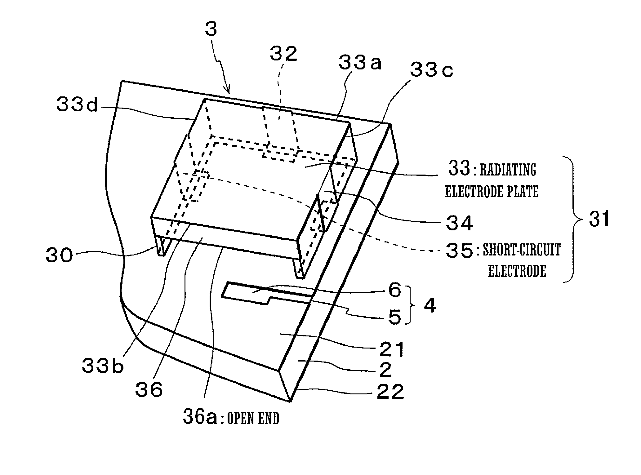
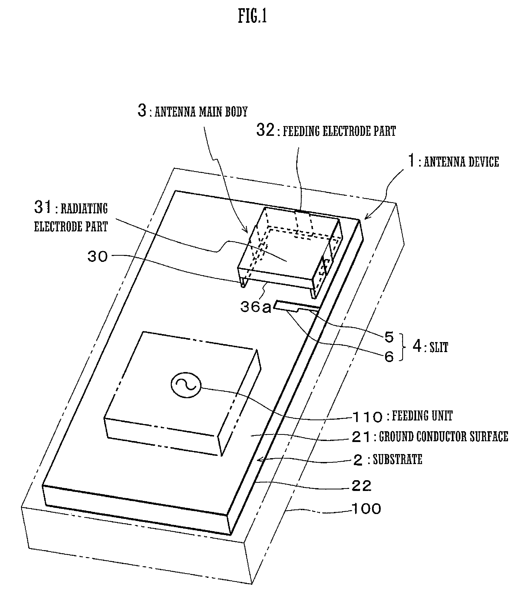
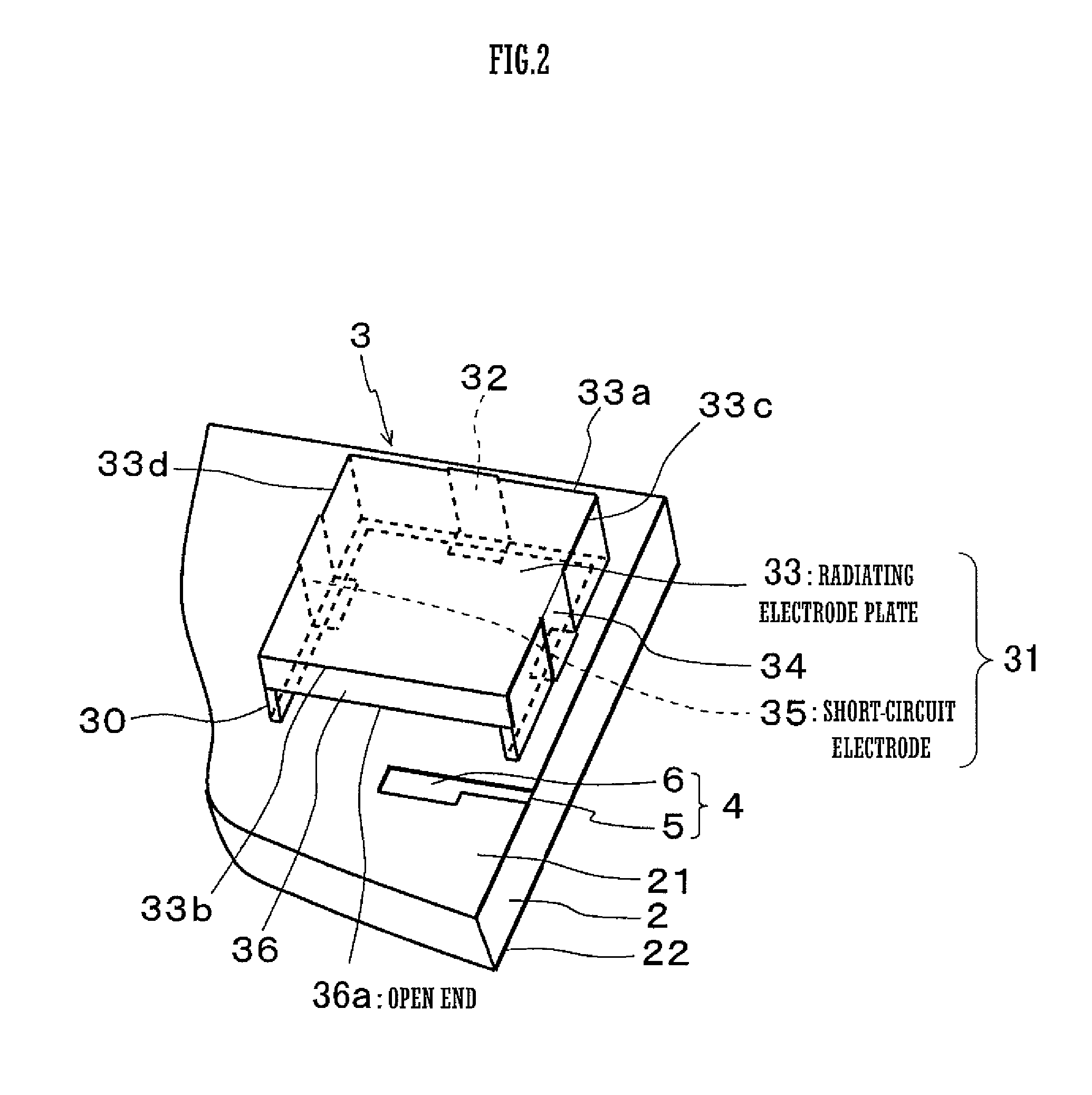
[0048]FIG. 1 is a schematic perspective view of an antenna device included in a wireless communication apparatus, according to a first preferred embodiment of the present invention. FIG. 2 is an enlarged perspective view of an antenna main body.
[0049]As illustrated in FIG. 1, the wireless communication apparatus is a mobile phone. An antenna device 1 according to the first preferred embodiment of the present invention is included in a housing 100 of the wireless communication apparatus. The wireless communication apparatus also includes other components, such as a keyboard, a microphone, a speaker, a liquid crystal panel, and various electronic circuits including a control unit, etc. These components will not be discussed or illustrated here, as they are known mechanisms. Hereinafter, only the antenna device 1 and its related mechanisms will be described.
[0050]The antenna device 1 includes a substrate 2, an antenna main body 3, and at least one slit 4.
[0051]The...
embodiment 2
Preferred Embodiment 2
[0090]Hereinafter, a second preferred embodiment of the present invention will be described.
[0091]FIG. 10 is a schematic plan view of an antenna device according to the second preferred embodiment of the present invention.
[0092]The present preferred embodiment is different from the first preferred embodiment in that the antenna main body 3 is mounted at a location other than a corner of the substrate 2.
[0093]Specifically, with the open end 36a of the radiating electrode plate 33 of the antenna main body 3 oriented in the longitudinal direction of the substrate 2, the antenna main body 3 is mounted closer to the center of the substrate 2. The at least one slit 4 is provided near the open end 36a of the radiating electrode plate 33.
[0094]The length L of the at least one slit 4 is preferably set to about one quarter of a wavelength at a frequency that is between two resonance frequencies of the antenna main body 3 and corresponds to the highest VSWR value.
[0095]Wi...
embodiment 3
Preferred Embodiment 3
[0104]Next, a third preferred embodiment of the present invention will be described.
[0105]FIG. 12 is a schematic plan view illustrating a main portion of an antenna device according to the third preferred embodiment of the present invention.
[0106]The present preferred embodiment is different from the above-described preferred embodiments in terms of the shape of the capacitive adjustment slit portion 5 of the at least one slit 4.
[0107]Specifically, as illustrated in FIG. 12, the inner edges 5a and 5b of the capacitive adjustment slit portion 5 of the at least one slit 4 each are formed into a shape of comb teeth, such that the inner edges 5a and 5b engage each other with a predetermined distance therebetween. Thus, the capacitive adjustment slit portion 5 is formed into a meandering shape.
[0108]This structure allows the inner edges 5a and 5b, each having a comb-tooth shape, to face each other. Since this increases the distance of a portion in which the inner ed...
PUM
 Abstract
Description
Claims
Application Information
 - R&D
- Intellectual Property
- Life Sciences
- Materials
- Tech Scout
- Unparalleled Data Quality
- Higher Quality Content
- 60% Fewer Hallucinations
Browse by: Latest US Patents, China's latest patents, Technical Efficacy Thesaurus, Application Domain, Technology Topic, Popular Technical Reports.
© 2025 PatSnap. All rights reserved.Legal|Privacy policy|Modern Slavery Act Transparency Statement|Sitemap|About US| Contact US: help@patsnap.com


