
Infrared imaging using thermal radiation from a scanning probe tip

Active Publication Date: 2010-02-25
BRUKER NANO INC
View PDF8 Cites 32 Cited by
  • Summary
  • Abstract
  • Description
  • Claims
  • Application Information

AI Technical Summary

Benefits of technology

[0011]In another embodiment the method includes modulating the relative distance between the probe tip and sample at a frequency and detecting radiation emitted from the probe and / or sample at that frequency and / or one or more of the harmonics of that frequency In a version of the method, the periodic modulation is induced by thermal bending of the probe. The detection of radiation at a modulation frequency and / or its harmonics can substantially reduce a background signal of emitted radiation.

Problems solved by technology

Conventional optical spectroscopy and microscopy, however, have been limited by optical diffraction.
For visible spectroscopy, the spatial resolution is typically limited to a few hundred nanometers, and for IR spectroscopy, spatial resolution is often limited to the scale of many microns.
Raman spectroscopy, however, is not currently as widely used as infrared spectroscopy.
Although this technique is quite promising, it does require an IR tunable pulsed light source, and such devices are. neither common nor inexpensive, as well as a complex optical system to deliver the radiation to a restricted region of the sample surface.
The use of an external light source typically requires complex opto-mechanical systems employing lenses and / or mirrors to focus the radiation, and actuators to align it with the probe tip and sample.
These requirements make the technique experimentally demanding and limits the accessible spectral range to the tuning range of the sources used.

Method used


Image

  • Infrared imaging using thermal radiation from a scanning probe tip
  • Infrared imaging using thermal radiation from a scanning probe tip
  • Infrared imaging using thermal radiation from a scanning probe tip

Examples


Embodiment Construction

Nanoscale Thermal Radiation Source

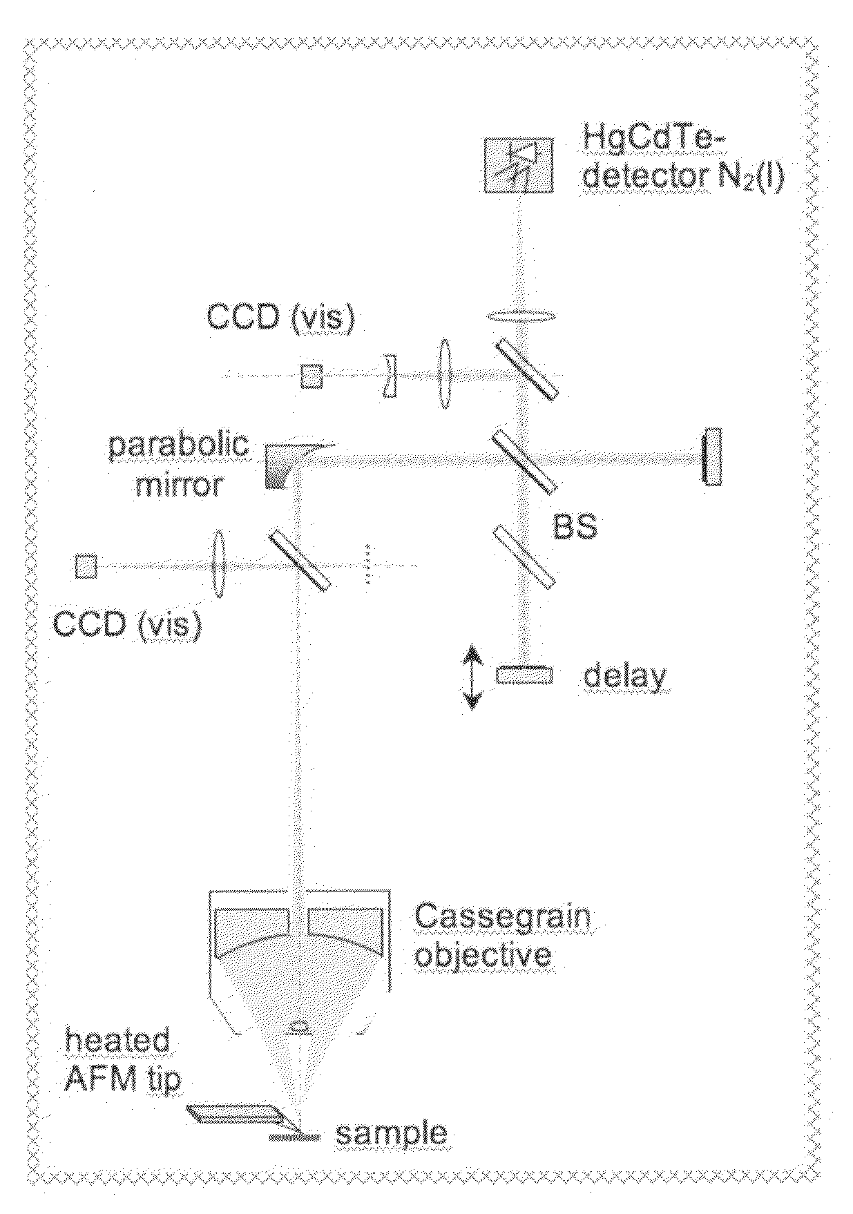
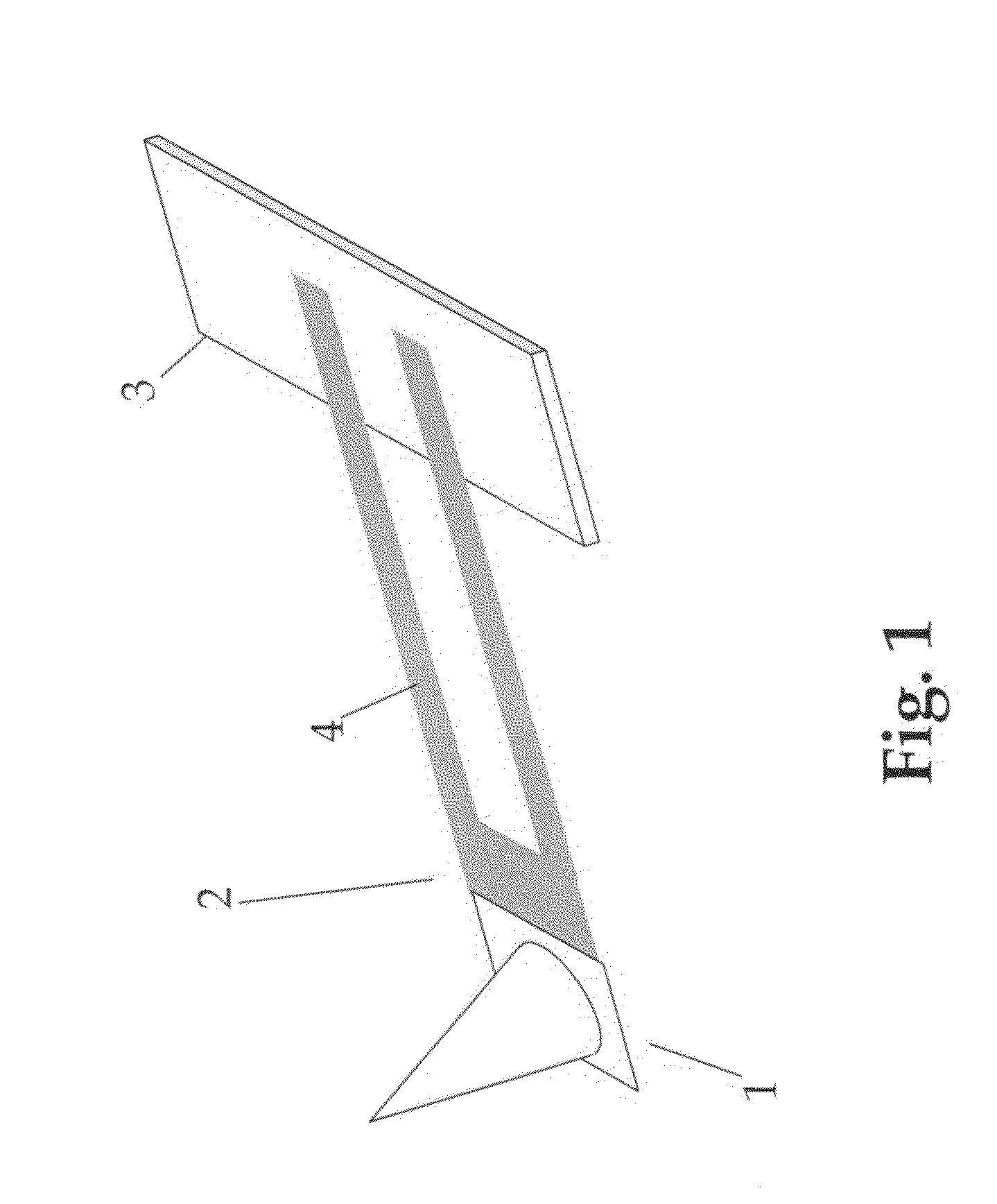
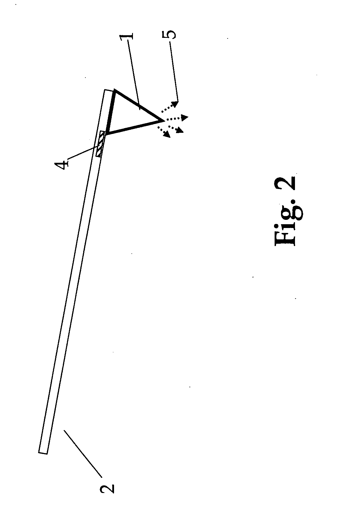
[0018]The invention is the use of thermal radiation from a heated scanning probe tip as a near-field source of radiation. The tip can be heated, e.g., electrically and / or optically to generate a local source of radiation that can interact with a region of a sample without requiring additional optics to focus and direct the radiation. As opposed to the use of external illumination by, e.g., a laser source, this provides high spectral bandwidth, saves the costs of an external light source, and is technologically easier to implement since only optics and alignment for far-field detection is required. In combination with spectrally resolved optical techniques (e.g., Fourier Transform spectroscopy) spectroscopic information with a simultaneous lateral optical image of the sample can be obtained.

[0019]In a particular embodiment, the heating of the probe tip can be accomplished conveniently with existing Nano thermal analysis (NanoTA) and / or Scanning Therm...


PUM


Abstract

A method for performing sub-micron optical spectroscopy, using a heated SPM probe and far-field collection optics is described. The enhanced emission characteristics at a sharp heated tip constitute a highly localized wideband IR source. Thus the IR absorption and emission properties of a sample surface adjacent can be observed and measured in the farfield even though the interaction region is sub-micron in scale. . . . providing spatial resolution mapping of sample composition.

Description

RELATED APPLICATIONS[0001]Not ApplicableFEDERALLY SPONSORED RESEARCH[0002]Not ApplicableSEQUENCE LISTING[0003]Not ApplicableBACKGROUND OF THE INVENTION[0004]This invention relates to optical near-field scanning probe microscopy and in particular to a method for performing spectroscopy on a very small, in some cases sub-micron region of a sample surface.[0005]Optical spectroscopy is a useful tool in many analytical fields such as polymer science and biology. Infrared spectroscopy, for example, is a benchmark tool used in science and industry to understand molecular composition and structure in fields including biology, chemistry and material science. Conventional optical spectroscopy and microscopy, however, have been limited by optical diffraction. For visible spectroscopy, the spatial resolution is typically limited to a few hundred nanometers, and for IR spectroscopy, spatial resolution is often limited to the scale of many microns. It would be particularly useful to perform IR sp...

Claims


Application Information

Patent Timeline
IPC IPC(8): G01J3/443G01J3/00
CPCB82Y35/00G01J3/02G01J3/0208G01J3/0243G01Q60/58G01J3/36G01J3/42G01J3/453G01Q30/02G01J3/108
Inventor RASCHKE, MARKUS B.
Owner BRUKER NANO INC
Learn More