Single-phase self-driven full-bridge synchrounous rectification
a synchronous rectification and self-driven technology, applied in the direction of dc network circuit arrangement, dc source parallel operation, efficient power electronics conversion, etc., can solve the defect of the circuit, the failure of the self-driven full-bridge sr to provide self-driven sr, and the contribution to the overall power loss of the power supply
- Summary
- Abstract
- Description
- Claims
- Application Information
AI Technical Summary
Benefits of technology
Problems solved by technology
Method used
Image
Examples
example 1
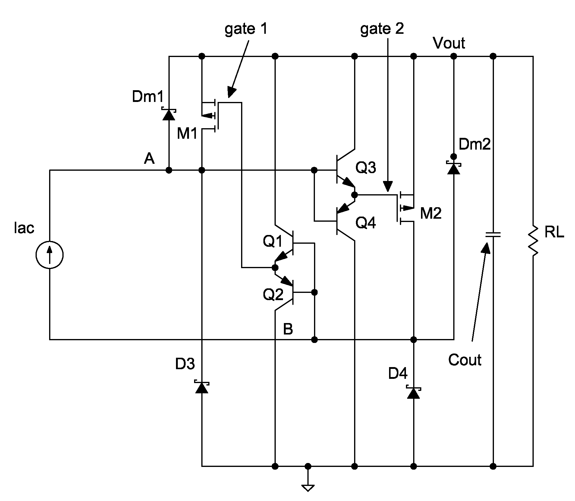
[0044]A first embodiment of the invention may take the form of a current-source input upper half VCSD full-bridge synchronous rectification (SR) as shown in FIG. 5
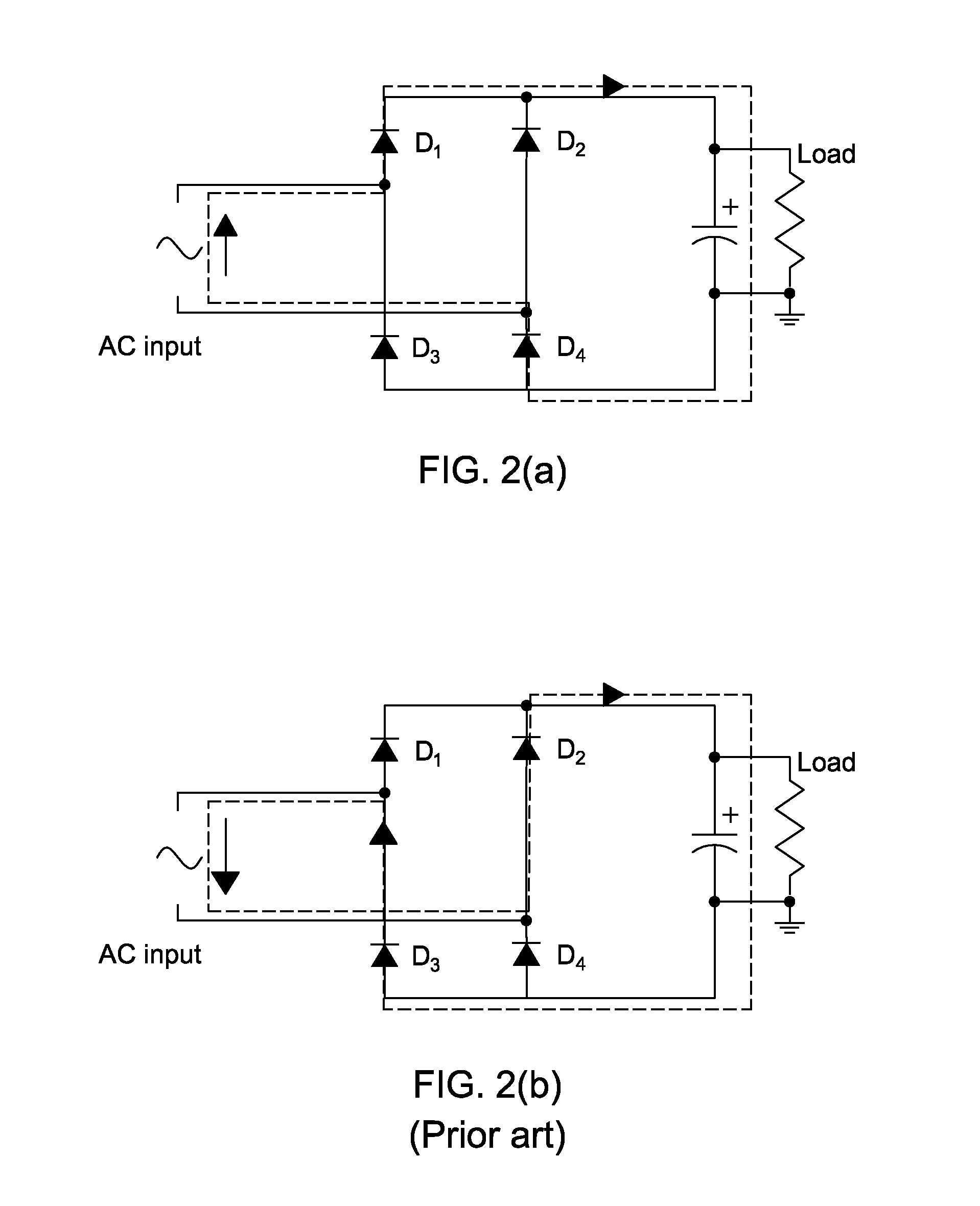
[0045]Two p-type power MOSFETs, M1 and M2, replace the upper diodes (D1 and D2 in FIG. 2) of the left and right branches of the diode-bridge. Dm1 and Dm2 can be either the body diode of the two MOSFETs or added external diodes. In this configuration MOSFET M1 has its gate signal controlled by VB and MOSFET M2 has its gate signal controlled by voltage VA. Both MOSFET gates are cross-connected against the current-source input terminals (point A and point B) through the complementary gate drive circuits formed by the Q1-Q2 pair and Q3-Q4 pair. A gate drive buffer (totem poles, drivers or direct connection) between the current-source input and the MOSFETs can be used to drive the power switches to be ON / OFF accordingly. In FIG. 6 and FIG. 7, at time t0 the current direction of the current source starts from point A to point B....
example 2
[0049]In order to further reduce the power loss in the diodes, a second embodiment of the invention comprises current-source input upper half VCSD and lower half ‘current controlled self-driven’ (CCSD) full-bridge synchronous rectification (SR) as shown in FIG. 9. In this case D3 and D4 in FIG. 5 are replaced with two n-type MOSFETs, M3 and M4, respectively.
[0050]As shown in FIG. 9, sensing resistors Rsen1 and Rsen2 are placed at both sides of the lower legs for detecting the current flow direction of M3 and M4 (defining positive current flow from ground up to Vout). Comparators U1 and U2 are used to produce driving pulses according to the current flow direction at Rsen1 and Rsen2. The voltage supplies of U1 and U2 can be directly derived from the rectified DC bulk voltage at the DC output, Vout, as this is the most cost effective method (or indirectly derived from an auxiliary power supply). A positive current through M3 and Dm3 or M4 and Dm4 will cause the output of comparator U1 ...
example 3
[0055]A third embodiment of the invention may take the form of voltage-source input upper half VCSD lower half CCSD full-bridge synchronous rectification as shown in FIG. 13.
[0056]The input of the proposed full-bridge SR can also be a voltage source, besides the current source in examples 1 and 2. A full version of voltage-source-input self-driven full-bridge SR is shown in FIG. 13. Sensing resistors Rsen1 and Rsen2 are placed at both the lower legs of the bridge for detecting the current flow direction (defining positive current flow from ground up to Vout). Comparator U1 and U2 are used to produce driving pulses according to the current flow direction at Rsen1 and Rsen2. A positive current at M3 and Dm3 or M4 and Dm4 will make output of comparator U1 or U2 go to high level. The high voltage level of the comparator, in turn, will drive the buffer Q5 or Q7 (totem pole or driver). Power switch M3 or M4 will be turned ON according to its positive current flow direction and it will be ...
PUM
 Abstract
Description
Claims
Application Information
 - R&D
- Intellectual Property
- Life Sciences
- Materials
- Tech Scout
- Unparalleled Data Quality
- Higher Quality Content
- 60% Fewer Hallucinations
Browse by: Latest US Patents, China's latest patents, Technical Efficacy Thesaurus, Application Domain, Technology Topic, Popular Technical Reports.
© 2025 PatSnap. All rights reserved.Legal|Privacy policy|Modern Slavery Act Transparency Statement|Sitemap|About US| Contact US: help@patsnap.com


