X-ray tube with backscatter protection

a technology of x-ray tube and backscatter protection, which is applied in the field of x-ray tube, can solve the problems of significant degradation of image quality that can be achieved with x-ray tube, thermal engineering protection of vacuum housing in opposition to the addition of heating of anodes, and inability to achieve continuous x-ray intensity, etc., and achieves high reliability and constant x-ray intensity

Inactive Publication Date: 2010-02-25
SIEMENS AG
View PDF1 Cites 16 Cited by
  • Summary
  • Abstract
  • Description
  • Claims
  • Application Information

AI Technical Summary

Benefits of technology

[0015]An object of the present invention is to provide an x-ray tube with an invariably constant x-ray intensity and a high reliability.
[0018]Due to the backscatter electron barrier device arranged according to the invention in the vacuum housing, the backscatter electrons are prevented from reaching the x-ray exit window.
[0021]An unwanted generation of extra-focal radiation in the volume penetrated by the usable x-ray radiation is reliably prevented by the barrier according to the invention.
[0023]Due to the smaller thickness of the x-ray exit window and the unnecessary cooling of the x-ray exit window, a higher intensity of the usable x-ray radiation is provided in the x-ray tube according to the invention.

Problems solved by technology

In particular, a considerable backscattering occurs at the impact point in high power x-ray tubes.
However, the thermal engineering protection of the vacuum housing is inevitably in opposition to the additional heating of the anode, since some of the electrons scatted back from the layer strike the anode.
If it is not masked by suitable countermeasures, the extra-focal radiation generated at the secondary impact points of the backscatter electrons leads to an (in part) significant degradation of the image quality that can be achieved with the x-ray tube.
However, a subsequent masking of the extra-focal radiation requires an additional, not insignificant effort and can often not be implemented depending on the application field of the x-ray tube.
This is particularly the case in applications that require a high exposure field and therefore can only be operated with a wide collimation, or in systems with variable focus position as they are used in high-resolution computer tomography.
When the cations strike the cathode, it can lead to impurities (contamination) and to direct mechanical damage.
Due to their geometric shape and their delicate [filigree] structure (approximately 10 nm in diameter and a few μm in length), the impurities can moreover lead to additional damages in field emitters that are produced from carbon nanotubes.
Even minor damage to the cathode leads to a degradation of the emission properties, and therefore to a degradation of the x-ray intensity.
A more severe damage inevitably leads to a failure of the x-ray tube.

Method used


Image

  • X-ray tube with backscatter protection
  • X-ray tube with backscatter protection

Examples


Embodiment Construction

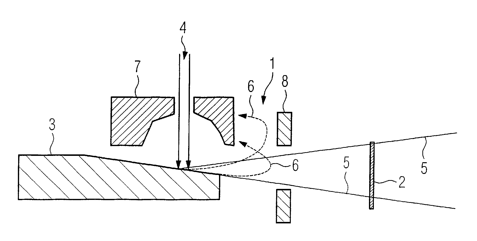
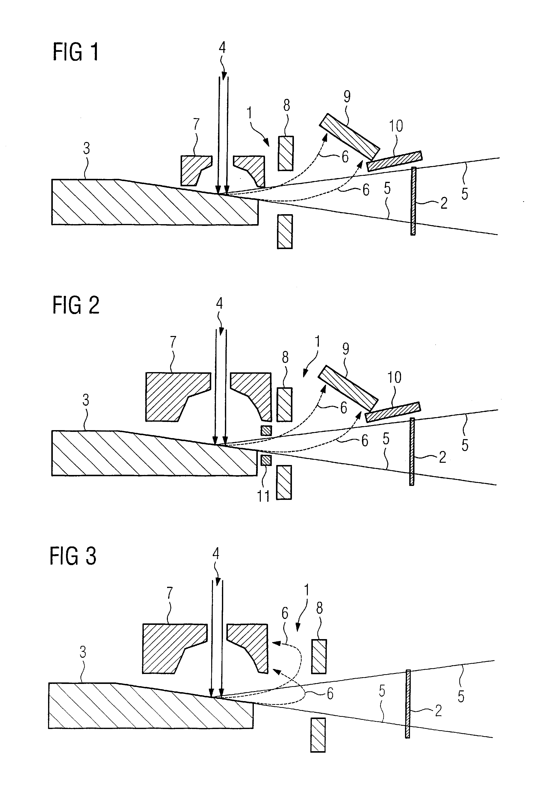
[0034]A backscatter electron capture device 1 that, according to the invention, is arranged in a vacuum housing of an x-ray tube is respectively shown in FIGS. 1 through 3 in the region of an x-ray exit window 2.

[0035]An anode 3 that generates usable x-ray radiation 5 upon impact of electrons 4 that were generated in an electron source (for example a cathode; not shown in FIGS. 1 through 3) is respectively arranged in the vacuum housing, which usable x-ray radiation 5 exits from the vacuum housing through the x-ray exit window 2.

[0036]Approximately 50% of the electrons 4 striking the anode 3 (which electrons generate the usable x-ray radiation) are scattered back. In the following these electrons are designated as backscatter electrons 6. Normally the backscatter electrons 6 possess no pronounced preferential direction; thus they scatter approximately isotropically in all spatial directions.

[0037]The backscatter electron capture device 1 respectively shown in FIGS. 1 through 3 affec...


PUM


Abstract

An x-ray tube has a vacuum housing containing an anode that generates usable x-ray radiation upon being struck by electrons generated by an electron source. The usable x-ray radiation escapes from the vacuum housing through an x-ray exit window. A backscatter electron barrier device arranged in the vacuum housing affects the backscatter electrons in the region of the usable x-ray radiation such that no backscatter electrons reach the x-ray exit window. Such an x-ray tube exhibits an invariably constant x-ray intensity and a high reliability.

Description

BACKGROUND OF THE INVENTION[0001]1. Field of the Invention[0002]The present invention concerns an x-ray tube with a vacuum housing in which an anode is arranged that generates x-ray radiation upon being struck by electrons generated by an electron source, the x-ray radiation exiting the vacuum housing through an x-ray exit window.[0003]2. Description of the Prior Art[0004]The generation of x-ray radiation in x-ray tubes typically ensues by bombardment of an anode with free electrons. The electrons are released from a cathode (thermionic emitter, field emitter) and accelerated to the desired primary energy by high voltage that is applied between the cathode and the anode. Upon the electrons striking the anode, the kinetic energy of the electrons is partially converted into x-ray radiation by the interaction of the electrons with the atomic nuclei of the anode. The yield of the generated x-ray radiation, i.e. the number of x-ray quanta over the entire energy range, exhibits a nearly l...

Claims


Application Information

Patent Timeline
Patent Type & Authority Applications(United States)
IPC IPC(8): H01J35/18
CPCH01J2235/168H01J35/16
Inventor FREUDENBERGER, JOERG
Owner SIEMENS AG
Why Eureka
Try Eureka