System and portable device for transmitting identification signals

a technology of identification signal and system, which is applied in the direction of transmission, electrical equipment, instruments, etc., can solve the problems of inability to tolerate large amplitude (i.e. high voltage), small amount of data can be transmitted, and low signal-to-noise ratio, so as to increase the battery life and save power consumption

Inactive Publication Date: 2010-02-25
DORMAKABA SCHWEIZ AG
View PDF15 Cites 27 Cited by
  • Summary
  • Abstract
  • Description
  • Claims
  • Application Information

AI Technical Summary

Benefits of technology

[0027]Now it has been recognized that such a charge recovery logic is particularly advantageous for the control—in general not integrated in the control electronics—of electrodes of a portable device according to the invention. This new approach is an object of the realization that with comparatively low frequencies that are required for intrabody communication, a control of the electrodes by means of a charge recovery system is possible and advantageous. It allows a substantial savings in power consumption and consequently realizes a clear increase in the battery life of the (autonomous, i.e. not connected to an external power supply) portable device.

Problems solved by technology

A disadvantage is, among other things, that as a result of the poor signal to noise ratio (literally: signal-interference ratio), only a small amount of data can be transmitted.
A good signal to noise ratio is only possible with a large amplitude of the transmission signal.
However, a large amplitude (i.e. high voltage) would not be tolerated by the user.
Despite these the bandwidth of the signal transmission remains limited.
This situation is unsatisfactory.

Method used


Image

  • System and portable device for transmitting identification signals
  • System and portable device for transmitting identification signals
  • System and portable device for transmitting identification signals

Examples


Embodiment Construction

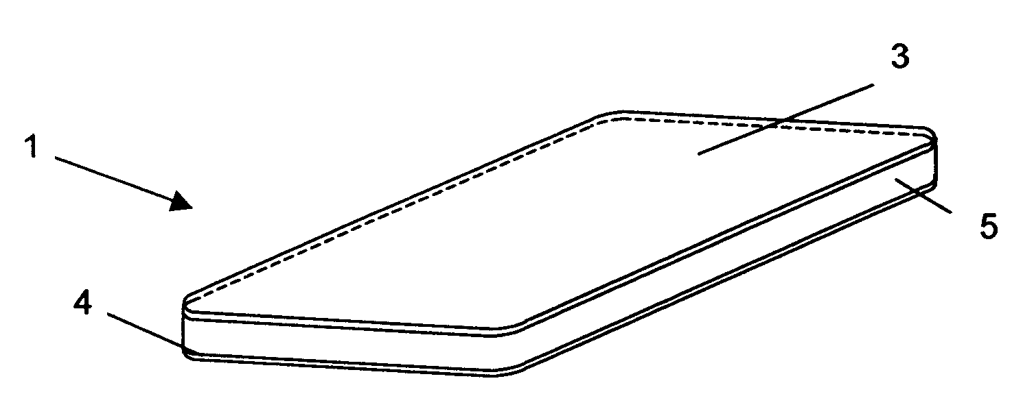
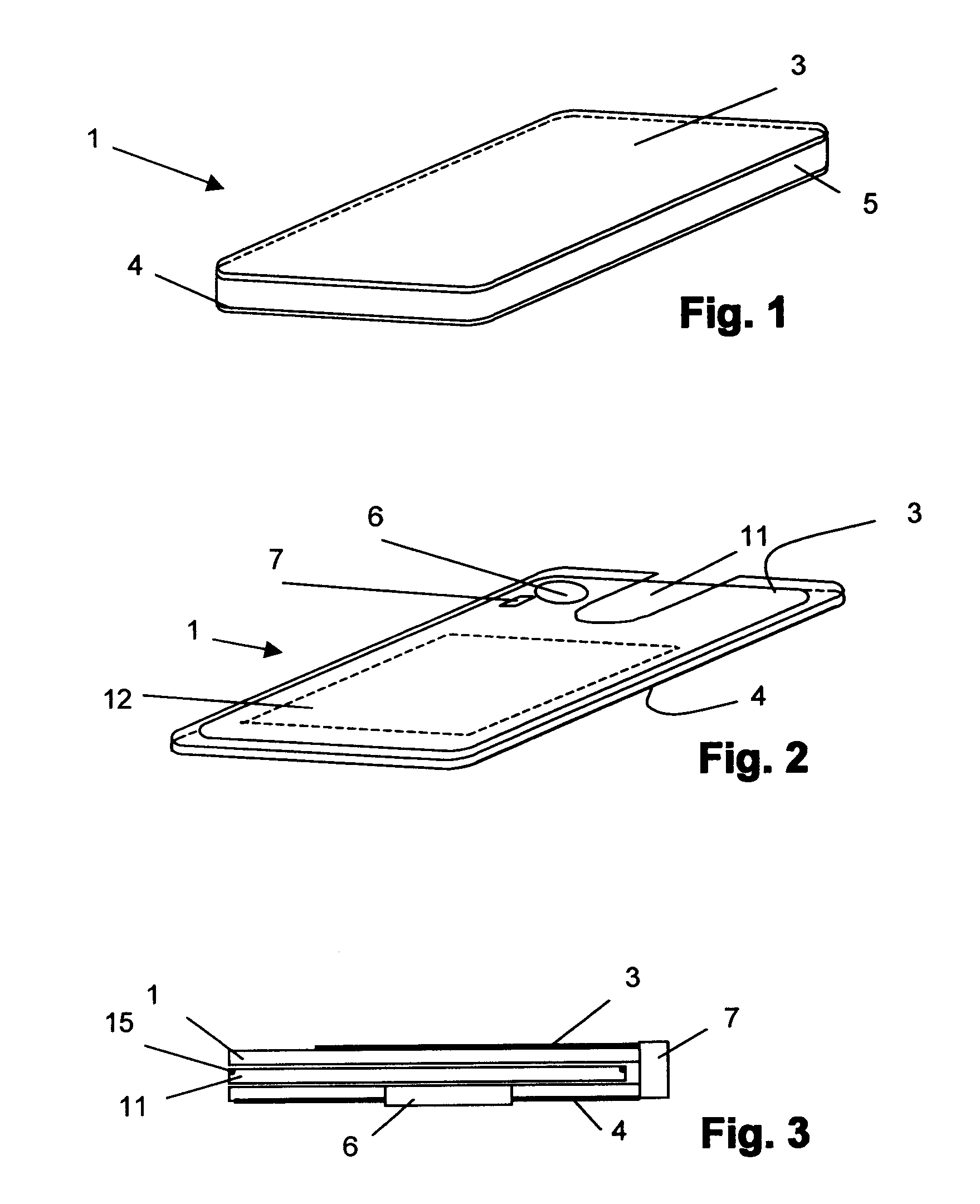
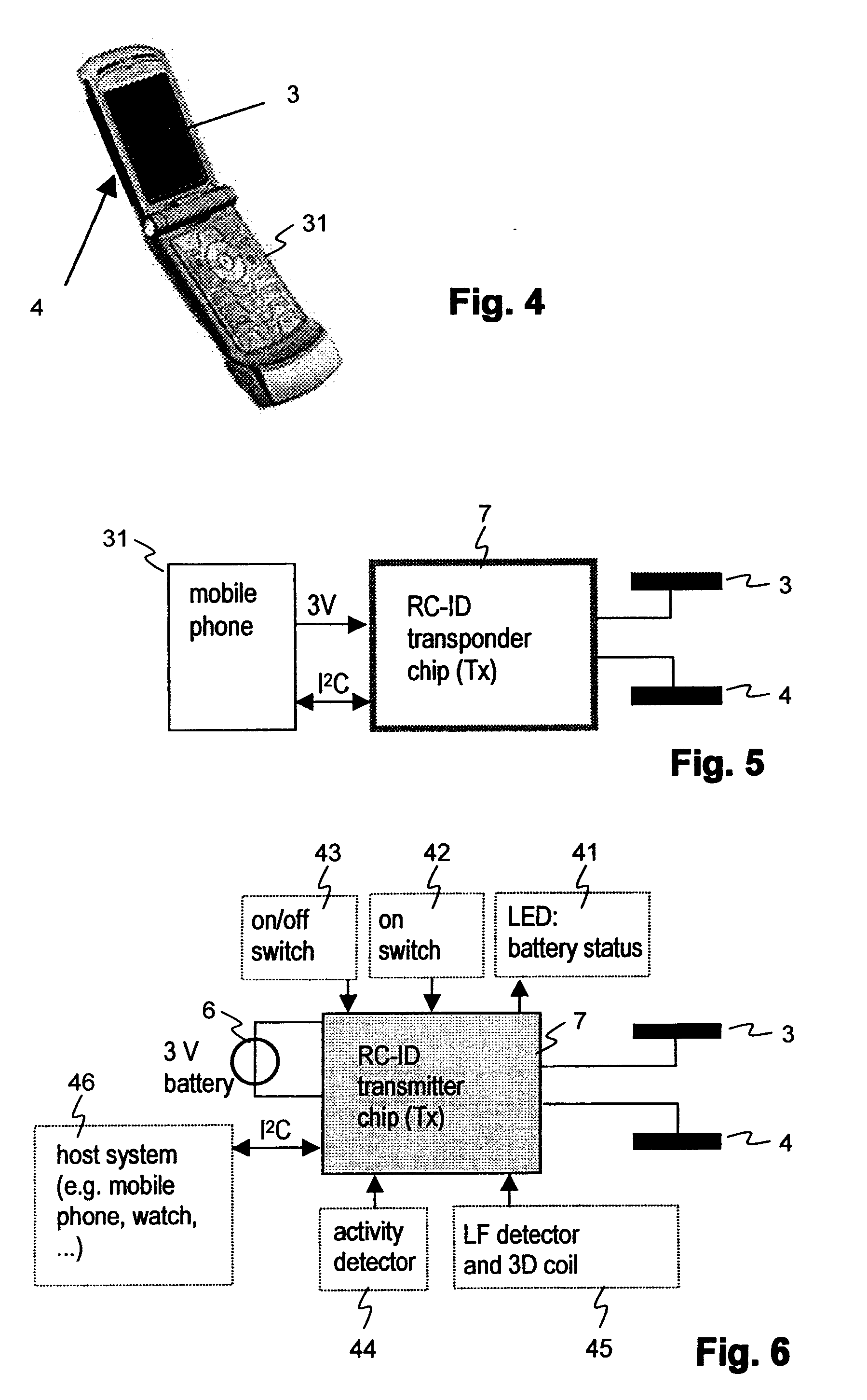
[0048]The portable device 1 according to FIG. 1 is in the depicted example designed in substantially a card shape and comprises a first electrode 3 and a second electrode 4. Between the first and the second electrode are arranged further elements, for example a plastic carrier 5 with integrated and / or applied electronic component parts and a battery compartment (not depicted in the figure). The integrated and / or applied electronic component parts can, for example, include the ASIC for control of the electrodes, an EEPROM memory, conductive pathways and / or further elements. Rather than plastic, the carrier can be of ceramic or of a different material, the important factor is simply that the two electrodes are electrically isolated from one another.

[0049]At least one of the electrodes can be at least partially transparent, in the depicted example, the first electrode 3. On an upper side of the plastic carrier 5, letters, pictures, etc. can be applied by known means such that they are ...


PUM


Abstract

A system is provided with a portable device (31) for the transmission of signals to a second device, wherein the portable device (31) is wearable on the body of a user. The portable device (31) includes at least two electrodes (3, 4) and transmitter electronics (7) for applying an electrical signal between the electrodes, in such a way that the signal between the electrodes (3, 4) is able to be coupled into the body of the user and detected by at least one electrode of the second device. The transmitter electronics are an application specific integrated circuit and thus include both means for the production of electrical signals that are dependent upon specified data, as well as means for applying the electrical signal between the electrodes. The means for generating electrical signals that are dependent upon specified data are typically digital circuits for the encoding of specified data that are to be transmitted and for the modulation of the data that are so encoded.

Description

BACKGROUND OF THE INVENTION[0001]1. Field of the Invention[0002]The invention relates to the communication between a sender (transmitter) and a receiver over a capacitive coupling (sometimes also referred to as capacitive resistive coupling, “intrabody” coupling or PAN-coupling) in which small electrical currents which are used for the transmission of information between the transmitter and the receiver are produced in the human body, and / or in which the transmitter and the receiver interact with one another over very short distances via electric fields.[0003]2. Description of Related Art[0004]This method of coupling is disclosed in the U.S. Pat. Nos. 4,591,854, 5,914,701 and 5,796,827. Implementations thereof are described in the international patent application PCT / CH 2006 / 000518 as well as in further published specifications of various bearers.[0005]A particular advantage of the capacitive coupling through the human body or, as the case may be, over short distances is the selecti...

Claims


Application Information

Patent Timeline
Patent Type & Authority Applications(United States)
IPC IPC(8): H04B5/00
CPCG07C9/00007H04B13/005G07C2009/00809G07C9/20
Inventor STUCKI, ANDREASHABERLI, ANDREAS
Owner DORMAKABA SCHWEIZ AG
Why Eureka
Try Eureka