Fuel gasification system

Inactive Publication Date: 2010-03-04
IHI CORP
View PDF1 Cites 11 Cited by
  • Summary
  • Abstract
  • Description
  • Claims
  • Application Information

AI Technical Summary

Benefits of technology

[0028]A fuel gasification system of the invention can exhibit excellent effects and advantages that tar contained in gasification gas can be efficiently decomposed without use of w

Problems solved by technology

However, recovery of tar by the scrubber 102 and tar/water separator 108 as mentioned above is costly in terms of wastewater treatment; more

Method used


Image

  • Fuel gasification system
  • Fuel gasification system
  • Fuel gasification system

Examples


embodiment 1

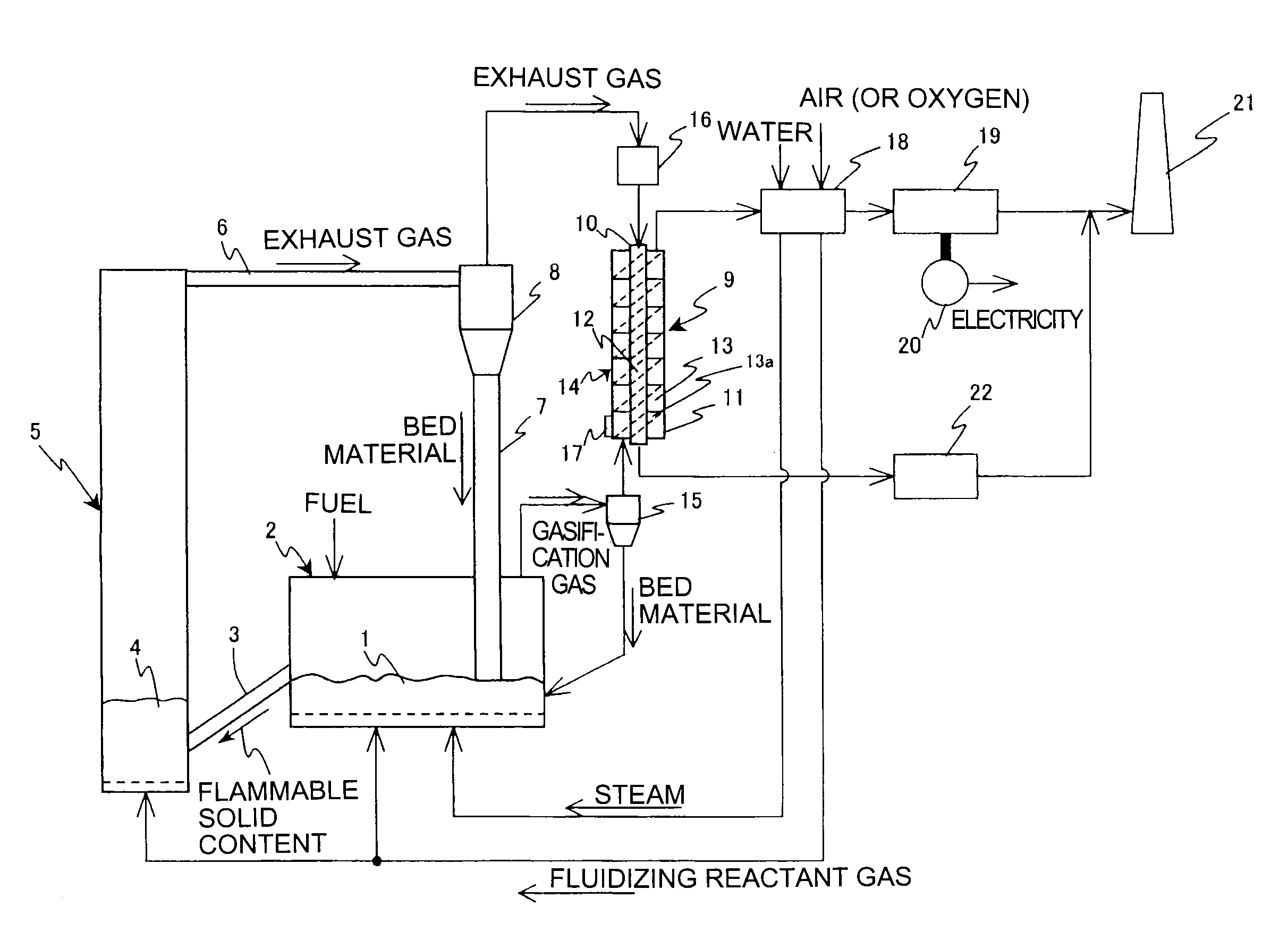
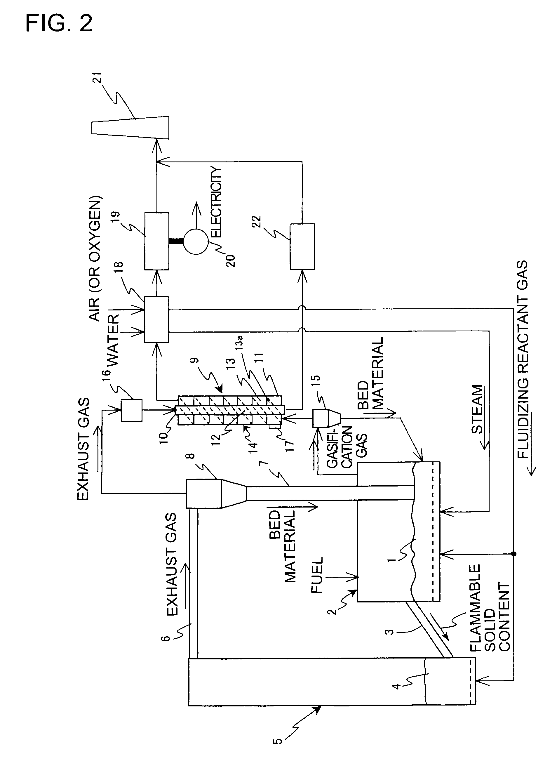
[0055]FIG. 2 shows a first embodiment a fuel gasification system according to the invention which comprises a gasification furnace 2 with a fluidized bed 1 formed therein through steam and fluidizing reactant gas such as air or oxygen so as to gasify charged fuel such as coal, biomass, waste plastic or various wet wastes into gasification gas and flammable solid content; a combustion furnace 5 into which the flammable solid content produced in the gasification furnace 2 is introduced via an introduction pipe 3 together with bed material and in which a fluidized bed 4 is formed by the fluidizing reactant gas to burn the flammable solid content; and a material separator 8 such as hot cyclone into which the exhaust gas is introduced from the combustion furnace 5 via an exhaust gas pipe 6 to be separated from the bed material which in turn is fed via a downcorner 7 into the gasification furnace 2, the fuel gasification system being provided with tar decomposing means 9 which heats the g...

embodiment 2

[0066]FIG. 3 shows a second embodiment of the invention in which parts identical with those shown in FIG. 2 are represented by the same reference characters, its fundamental structure being similar to that shown in FIG. 2. The present embodiment is characteristic as shown in FIG. 3 in that tar decomposing means 9 is constituted by a heat exchanger 23 which heats, by heat of a combustion furnace 5, gasification gas introduced into a gasification gas passage 13 which in turn is formed on an inner surface of the furnace 5. It goes without saying that the gasification gas passage 13 on the inner surface of the furnace 5 may be, as needs demand, in the form of spiral passage just like the embodiment of FIG. 2 so as to prolong the dwell time of the gasification gas in the heat exchanger 23.

[0067]In the embodiment shown in FIG. 3, the gasification gas produced in a gasification furnace 2 and separated from the bed material in a material separator 15 is introduced into the gasification gas ...

embodiment 3

[0068]FIG. 4 shows a third embodiment of the invention in which parts identical with those shown in FIG. 2 are presented by the same reference characters, its fundamental structure being similar to that shown in FIG. 2. The present embodiment is characteristic as shown in FIG. 4 in that tar decomposing means 9 is constituted by a heat exchanger 24 which heats, by heat of a combustion furnace 5, gasification gas introduced into a gasification gas passage 13 which in turn is formed on an outer surface of the furnace 5. In the embodiment of FIG. 4, the gasification gas passage 13 formed on the outer surface of the furnace 5 is in the form of a spiral passage 13a with heat storage material (not shown) so that high temperature can be retained while dwell time of the gasification gas in the heat exchanger 24 is secured. An exhaust gas passage 12 is formed on an outer surface of the gasification gas passage 13 of the heat exchanger 24 so as to introduce exhaust gas from the combustion furn...


PUM


Abstract

A fuel gasification system including a gasification furnace including a fluidized bed formed by fluidizing reactant gas for gasifying fuel charged into gasification gas and flammable solid content, a combustion furnace for combustion of the flammable solid content into which the flammable solid content produced in the furnace is introduced together with bed material and that includes a fluidized bed formed by fluidizing reactant gas, a material separator such as hot cyclone that separates bed material from exhaust gas introduced from the combustion furnace, the separated bed material being fed through a downcorner to the gasification furnace, and a tar decomposing mechanism that heats the gasification gas produced in the furnace to decompose tar contained in the gasification gas.

Description

TECHNICAL FIELD [0001]The present invention relates to a fuel gasification system.BACKGROUND ART [0002]A fuel gasification system has been developed to produce gasification gas, using coal, biomass, waste plastic, various wet wastes or the like as fuel.[0003]In the fuel gasification system, tar is contained in gasification gas produced in a gasification furnace. Especially heavy oil component of the tar is highly viscous and tends to attach to piping or the like, resulting disadvantageously in clogging of the piping or the like in a long-term operation.[0004]In order to overcome such disadvantage, there has been, for example, a fuel gasification system as shown in FIG. 1 which comprises a gasification furnace 100 for partly oxidizing fuel such as coal, biomass, waste plastic or various wet wastes into gasification gas, a steam generator 101 for generating steam to be fed to the furnace 100, a scrubber 102 for separating tar and the like from the gasification gas produced in the furn...

Claims


Application Information

Patent Timeline
IPC IPC(8): C10J3/72
CPCC10J3/482C10J3/485C10J3/56C10J3/721C10J2300/0956C10J3/84C10J2300/0973C10J2300/0993C10J2300/1671C10J2300/1807F27B15/00C10J2300/0959
Inventor MURAKAMI, TAKAHIROKYO, KOUBUNSUDA, TOSHIYUKI
Owner IHI CORP
Why Eureka
Try Eureka