Wastewater Lagoon Aeration System

a technology for aeration systems and wastewater lagoons, applied in the direction of feeding/discharge of settling tanks, water treatment parameter control, specific water treatment objectives, etc., can solve the problems of plastic or asphalt or concrete liners and are costly to construct, serious environmental problems, health hazards

Active Publication Date: 2010-03-04
KORZENIOWSKI JAN A
View PDF11 Cites 4 Cited by
  • Summary
  • Abstract
  • Description
  • Claims
  • Application Information

AI Technical Summary

Benefits of technology

[0035]The flow rates and the retention capacities of the system components may vary depend

Problems solved by technology

The conventional lagoons require a large area, impermeable soil or synthetic plastic or asphalt or concrete liners and are costly to construct.
Lagoons which are not watertight may cause serious environmental problems of contamination of soil and ground and surface waters, and become a health hazard.
The c

Method used


Image

  • Wastewater Lagoon Aeration System
  • Wastewater Lagoon Aeration System
  • Wastewater Lagoon Aeration System

Examples


first embodiment

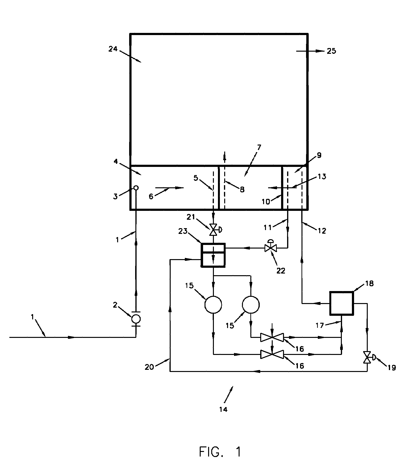
[0044]the invention is shown on FIG. 1. The treatment system primarily comprises a raw wastewater inlet pipe, generally indicated by the reference numeral 1, a primary settling cell 4, a clarification (secondary settling) cell 7, a sludge return cell 9, an anoxic tank 23, and an aeration system 14 which comprises aeration pumps 15, air aspirator-mixers 16 and an aeration tank 18. The treatment system may also include a new or an existing treated wastewater storage cell 24.

[0045]The raw wastewater inlet pipe 1 may be provided with a flow meter 2, and a single or multiple inlet 3 into the primary settling cell 4.

[0046]On the opposite side of the inlet 3, an outlet pipe 5 is located in the primary settling cell 4, preferably throughout the entire adjacent side of the cell 4 and with adequate perforation or multiple inlet nozzles to promote a “plug” like flow, indicated by an arrow 6, through the cell 4.

[0047]The settled raw wastewater flows from the primary settling cell 4 to the aerat...

second embodiment

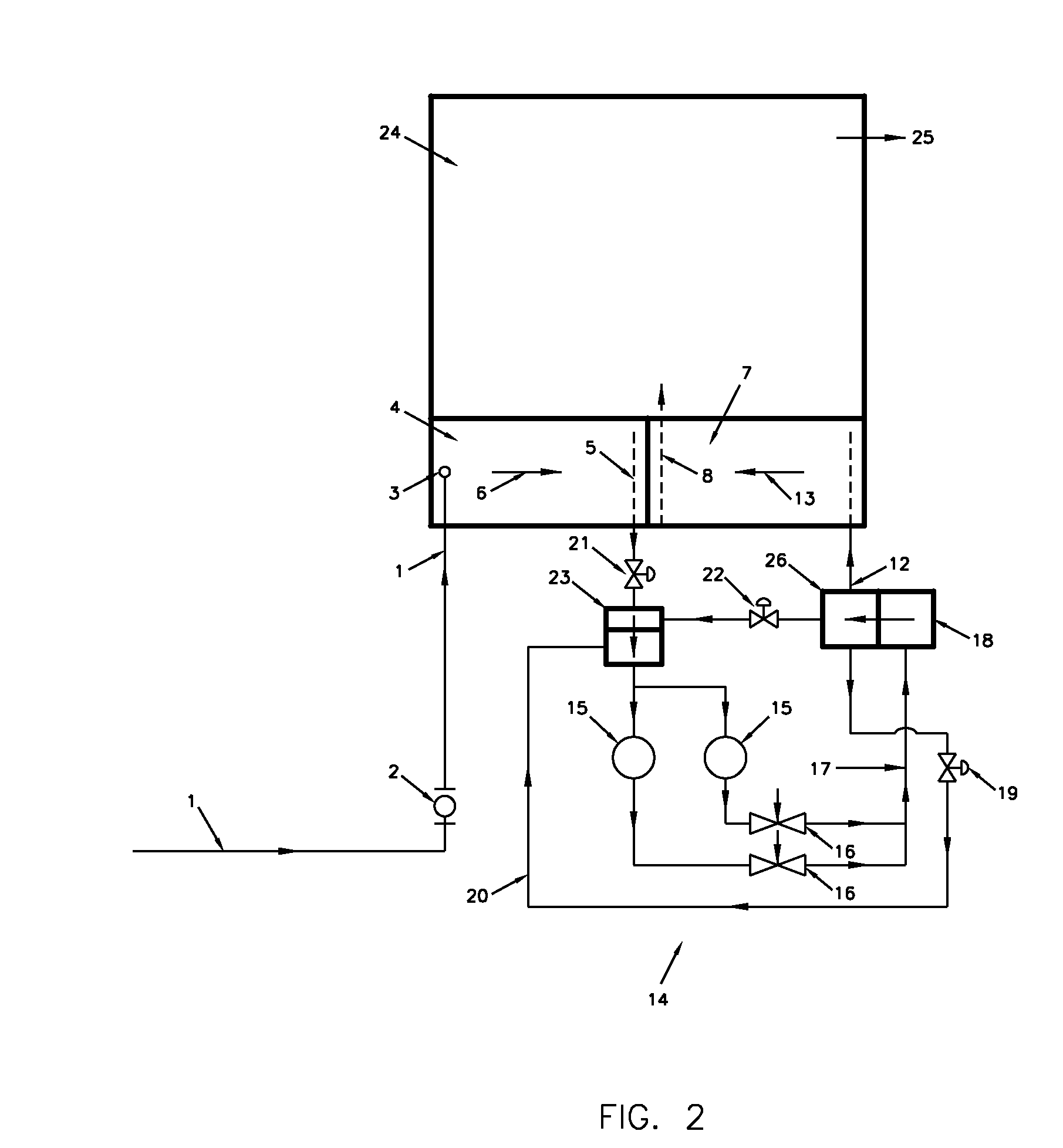
[0056]the invention is shown on FIG. 2.

[0057]For the various embodiments disclosed here, the same reference numerals are used for the same or substantially similar features. Hence, the raw wastewater inlet pipe 1, the primary settling cell 4, the control valve 21, and the anoxic tank 23 are in essence the same as those shown and described in FIG. 1. The clarification (secondary settling) cell 7 and the aeration system 14 are similar to those shown and described in FIG. 1.

[0058]The treatment system, according to this embodiment, primarily comprises the raw wastewater inlet pipe 1, the primary settling cell 4, the clarification (secondary settling) cell 7, the anoxic tank 23 and the aeration system 14.

[0059]The treatment system may also include a new or existing treated wastewater primary storage cell 24.

[0060]The aeration system 14, comprises the aeration pumps 15, the air aspirator-mixers 16, the aeration tank 18, a sludge return tank 26, the recirculation by-pass pipe 20, the contr...

third embodiment

[0068]the invention is shown on FIG. 3 and FIG. 3A.

[0069]For the various embodiments disclosed here, the same reference numerals are used for the same or substantially similar features. Hence, the raw wastewater inlet pipe 1 is in essence the same as that shown in FIG. 1 and FIG. 2 and the aeration system 14 is similar to that shown on FIG. 1 and FIG. 2. Also, the wastewater inlet and outlet pipes 5&12 located in the lagoon are similar to those shown on FIG. 1&FIG. 2.

[0070]The treatment system, according to this embodiment, primarily consists of the raw wastewater inlet pipe 1, a settling and aeration cell 27, and the aeration system 14.

[0071]The treatment system is provided for an extended aeration treatment process.

[0072]The treatment system may also include a storage cell 28.

[0073]The settling and aeration cell 27 is provided for settling of the primary suspended solids and the bio-mass suspended solids (bacteria) produced during the treatment process and for aeration and recircu...


PUM

PropertyMeasurementUnit
Flow rateaaaaaaaaaa
Volumeaaaaaaaaaa
Strengthaaaaaaaaaa

Abstract

A novel, economical, efficient and versatile lagoon aeration system is provided which can be used with existing or new wastewater (sewage) lagoons to increase the lagoons treatment efficiency and capacity, and to allow for a continuous, year round discharge of treated wastewater to environment. The system can be operated in warm and cold climates for treatment of municipal and industrial wastewaters of varying strength and flow rates in a secondary activated sludge treatment process or in a tertiary activated sludge treatment process, or an extended aeration treatment process. The system employs patented (Patent No: U.S. Pat. No. 6,969,052 B2) Air Aspirator-Mixer (AAM) which provides highly efficient wastewater aeration outside the lagoon which facilitates an easy and economical operation and maintenance of the system throughout the year.

Description

FIELD OF THE INVENTION[0001]The invention relates to a process and apparatus for aeration of municipal and industrial wastewaters in lagoons (stabilization ponds) to accomplish the wastewater treatment to secondary or tertiary treatment standards.BACKGROUND OF THE INVENTION[0002]Wastewater lagoons or stabilization ponds provide the simplest and the oldest wastewater treatment for municipal and industrial wastewaters which support bacteriological activity and decomposition, and reduction of organic matter.[0003]Wastewater lagoons are primarily used for wastewater treatment by small municipalities and industries, where adequate land is available.[0004]Wastewater lagoons are typically known as conventional lagoons and aerated lagoons.[0005]In the conventional lagoons, aeration of the wastewater is not used and in the aerated lagoons the wastewater is aerated inside the lagoons, for a period of several days to several weeks, depending on the climatic conditions and strength of the waste...

Claims


Application Information

Patent Timeline
IPC IPC(8): C02F9/14
CPCC02F1/008C02F3/1257C02F2209/08C02F2303/10C02F2209/16C02F2209/18C02F2209/10Y02W10/10Y02W10/30
Inventor KORZENIOWSKI, JAN A
Owner KORZENIOWSKI JAN A
Why Eureka
Try Eureka