Bottom gate type thin film transistor, method of manufacturing the same, and display apparatus
a thin film transistor and bottom gate technology, applied in the direction of transistors, electroluminescent light sources, electric lighting sources, etc., can solve the problems of high etching speed, difficult to produce a large-area tft with high yield, and damage to the oxide semiconductor layer, etc., to achieve the effect of achieving mass production
- Summary
- Abstract
- Description
- Claims
- Application Information
AI Technical Summary
Benefits of technology
Problems solved by technology
Method used
Image
Examples
example 1
[0141]In this example, an inverted stagger (bottom gate) type MISFET device illustrated in FIG. 11 is produced.
[0142]First, a gate terminal of Ti of 5 nm / Au of 40 nm / Ti of 5 nm is formed on a glass substrate by photolithography and a lift-off technique.
[0143]Further, an insulating layer of a-SiOx with a thickness of 200 nm is formed thereon by sputtering. In this case, a SiO2 target is used as the sputtering target, and Ar gas is used as the sputtering gas. Also the RF radio-frequency power is 400 W, the deposition pressure is 0.1 Pa, and the film deposition rate is 7.4 nm / min. The substrate temperature is room temperature, and no intentional heating is performed.
[0144]Further, an amorphous oxide semiconductor film used as a semiconductor layer is formed thereon at room temperature with a thickness of 20 nm by an RF sputtering.
[0145]A channel region is formed by photolithography and wet etching using hydrochloric acid.
[0146]After that, Ti of 5 nm / Au of 40 nm / Ti of 5 nm is formed by ...
example 2
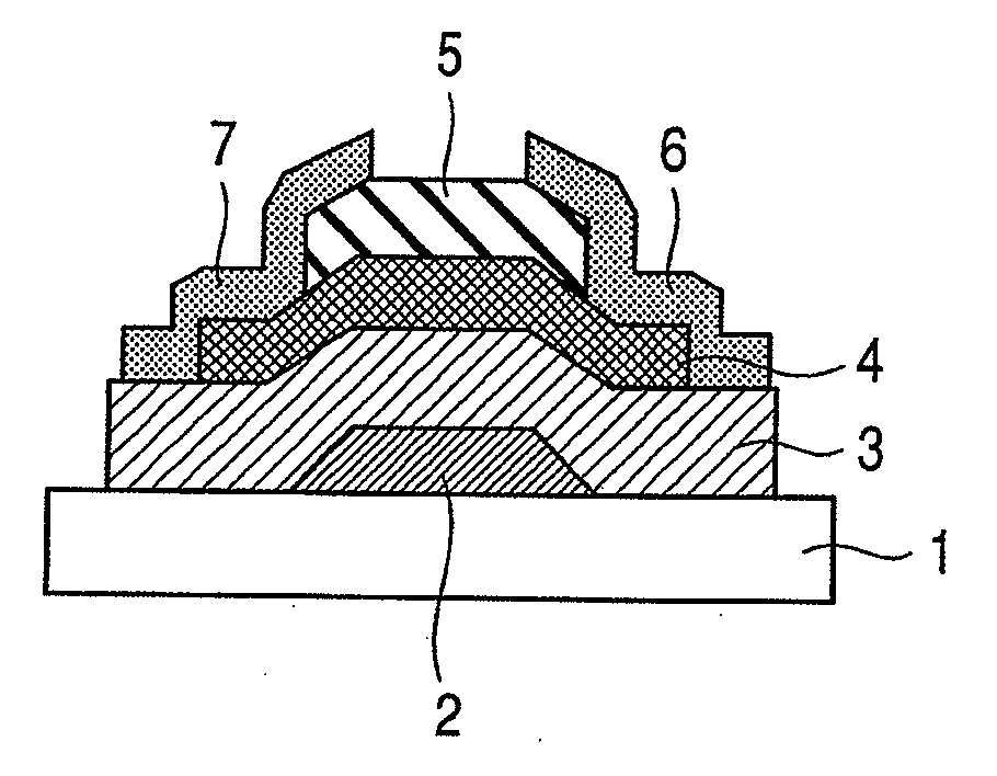
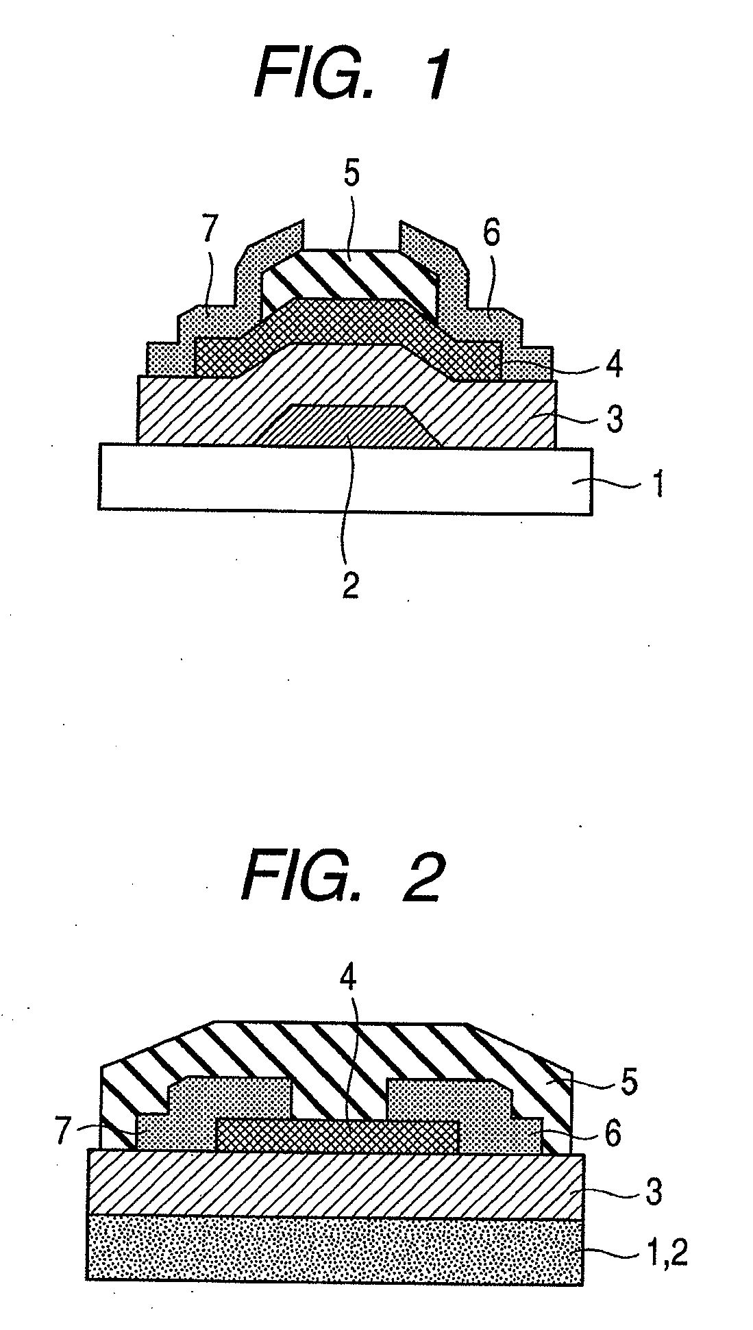
[0160]In this example, an inverted stagger (bottom gate) type MISFET device illustrated in FIG. 1 is produced.
[0161]First, a gate electrode layer of a transparent conductive film IZO with a thickness of 150 nm is formed on a glass substrate by sputtering.
[0162]A gate electrode is formed by photolithography and wet etching using hydrochloric acid.
[0163]Further, an insulating layer of a-SiOx with a thickness of 200 nm is formed thereon by an RF sputtering. In this case, a SiO2 target is used as the sputtering target, and Ar gas is used as the sputtering gas. Also the RF radio-frequency power is 400 W, the deposition pressure is 0.1 Pa, and the film deposition rate is 7.4 nm / min. The substrate temperature is room temperature, and no intentional heating is performed.
[0164]Further, an amorphous oxide semiconductor film used as a semiconductor layer is formed at room temperature with a thickness of 20 nm by sputtering.
[0165]A channel region is formed by photolithography and wet etching us...
example 3
[0172]In this example, a display apparatus using the TFT illustrated in FIG. 7 is described.
[0173]The production process of the TFT is similar to that of Example 3.
[0174]In the above-described TFT, a short side of an ITO film forming a drain electrode is extended to 100 μm. With 90 μm of the extended portion being left and with wiring to the source electrode and the gate electrode being secured, the TFT is covered with an insulating layer.
[0175]A polyimide film is applied thereon and rubbing is carried out.
[0176]On the other hand, a plastic substrate having an ITO film and a polyimide film similarly formed thereon with rubbing carried out is prepared, the plastic substrate is opposed to the above-described substrate having the TFT formed thereon with a gap of 5 μm therebetween, and nematic liquid crystal is injected into the gap.
[0177]Further, a pair of polarizing plates is provided on both sides of the structure.
[0178]In this case, by applying voltage to the source electrode of the...
PUM
 Abstract
Description
Claims
Application Information
 - R&D
- Intellectual Property
- Life Sciences
- Materials
- Tech Scout
- Unparalleled Data Quality
- Higher Quality Content
- 60% Fewer Hallucinations
Browse by: Latest US Patents, China's latest patents, Technical Efficacy Thesaurus, Application Domain, Technology Topic, Popular Technical Reports.
© 2025 PatSnap. All rights reserved.Legal|Privacy policy|Modern Slavery Act Transparency Statement|Sitemap|About US| Contact US: help@patsnap.com


