Programmable frequency divider and frequency dividing method thereof

Active Publication Date: 2010-03-04
KOREA UNIV IND & ACADEMIC CALLABORATION FOUND
View PDF8 Cites 17 Cited by
  • Summary
  • Abstract
  • Description
  • Claims
  • Application Information

AI Technical Summary

Benefits of technology

[0014]The present invention provides a programmable frequency divider and a frequency dividing method thereof, which can significantly reduce power consumption, in order

Problems solved by technology

Since such a programmable divider divides a high-speed clock generated by a voltage-controlled oscillator (generally called “VCO”), power consumption is very high.
However, the existing programmable divider has very high fan-out since the DMP supplies clocks divided by itself simultaneously to the two counters (that is, the SC and PC), as described above.
Due to such ver

Method used


Image

  • Programmable frequency divider and frequency dividing method thereof
  • Programmable frequency divider and frequency dividing method thereof
  • Programmable frequency divider and frequency dividing method thereof

Examples


Embodiment Construction

[0030]Prior to detailed description of the present invention, for easy understanding, an outline of a solution for achieving an object of the present invention will be described below.

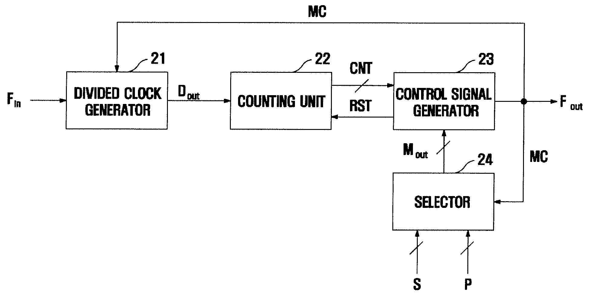
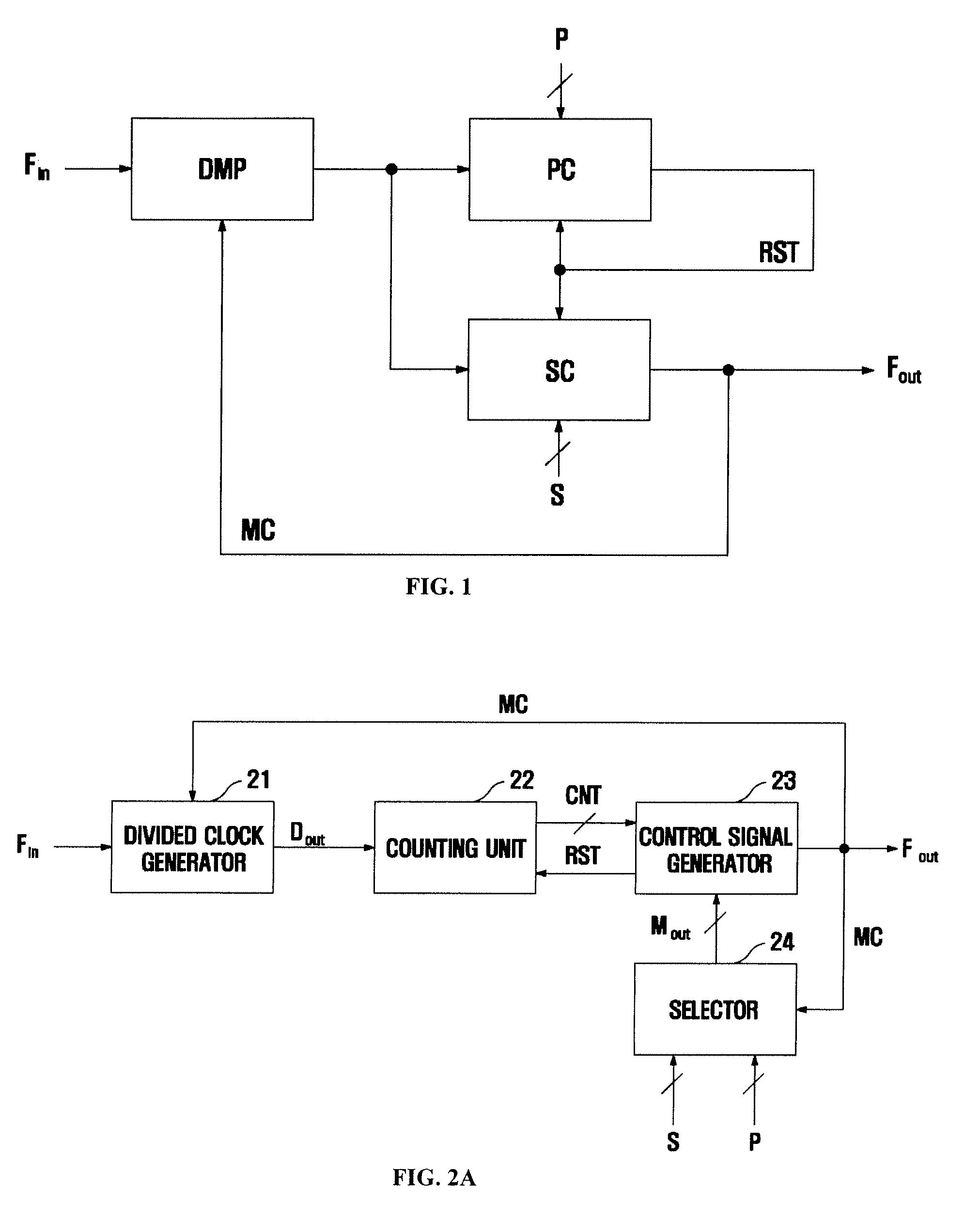
[0031]A programmable frequency divider according to the present invention is aimed at low power consumption. An outline of a solution for achieving an object of the present invention is to reduce high fan-out and high power consumption caused by two counters (a program counter and swallow counter) used in the existing frequency divider by replacing the two counters by one counter module to perform swallow mode counting and program mode counting sequentially for low power consumption.

[0032]The invention is described more fully hereinafter with reference to the accompanying drawings, in which exemplary embodiments of the invention are shown. This invention may, however, be embodied in many different forms and should not be construed as limited to the exemplary embodiments set forth herein. Rather, these ...


PUM


Abstract

Provided are a programmable frequency divider, more particularly, a programmable frequency divider which is a core module of a frequency synthesizer using a Phase Locked Loop (PLL) for generating very high frequencies.
The programmable frequency divider includes: a divided clock generator dividing a frequency of an input clock signal Fin at a first divide ratio (N+1) or a second divide ratio N according to a divide ratio control signal MC to generate a plurality of divided clock signals Dout; a counting unit counting the number CNT of the plurality of divided clock signals Dout, by performing swallow mode counting and program mode counting sequentially on the plurality of divided clock signal Dout; a control signal generator generating the divide ratio control signal MC, using the number CNT of the plurality of divided clock signal Dout a count S by the swallow mode counting and a count P by the program mode counting, the count P corresponding to a maximum of the number CNT, feeding the divide ratio control signal MC back to the divided clock generator, and generating a reset control signal RST for resetting the counting unit.

Description

CROSS-REFERENCE TO RELATED APPLICATIONS[0001]This application claims all benefits of Korean Patent Application No. 10-2008-0086297 filed on Sep. 2, 2008 in the Korean Intellectual Property Office, the disclosures of which are incorporated herein by reference.BACKGROUND OF THE INVENTION[0002]1. Field of the Invention[0003]The present invention relates to a Programmable Frequency Divider (PFD) and a frequency dividing method thereof, and more particularly, to a programmable frequency divider which is a core module of a frequency synthesizer using a Phase Locked Loop (PLL) for generating very high frequencies, and a frequency dividing method thereof.[0004]2. Description of the Related Art[0005]With the recent development of mobile communication environments, frequency synthesizers allowing standards, such as a Global System for Mobile communications (GSM), Global Positioning System (GPS), DCS 1800, Wideband Code-Division Multiple Access (WCDMA), and wireless LAN, etc., to stably operat...

Claims


Application Information

Patent Timeline
IPC IPC(8): H03K21/00H03B19/00
CPCH03K21/38H03L7/193H03K23/68H03K23/667H03K23/00H03L7/183
Inventor KIM, SOO-WONKIM, KYU-YOUNG
Owner KOREA UNIV IND & ACADEMIC CALLABORATION FOUND
Why Eureka
Try Eureka