

Magnetic nanoparticles, bulk nanocomposite magnets, and production thereof
a technology of nanocomposite magnets and magnetic nanoparticles, which is applied in the direction of magnetism of magnetic bodies, magnetic materials, inorganic material magnetism, etc., can solve the problems of difficult grain alignment of hard magnetic phases, difficult to control the critical length, and limited success of chemical synthesis methods in the synthesis of hard magnetic nanoparticles of rare-earth compounds
- Summary
- Abstract
- Description
- Claims
- Application Information
AI Technical Summary
Problems solved by technology
Method used
Image

Examples
example 1
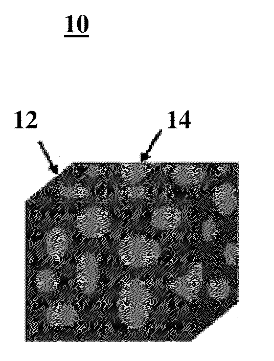
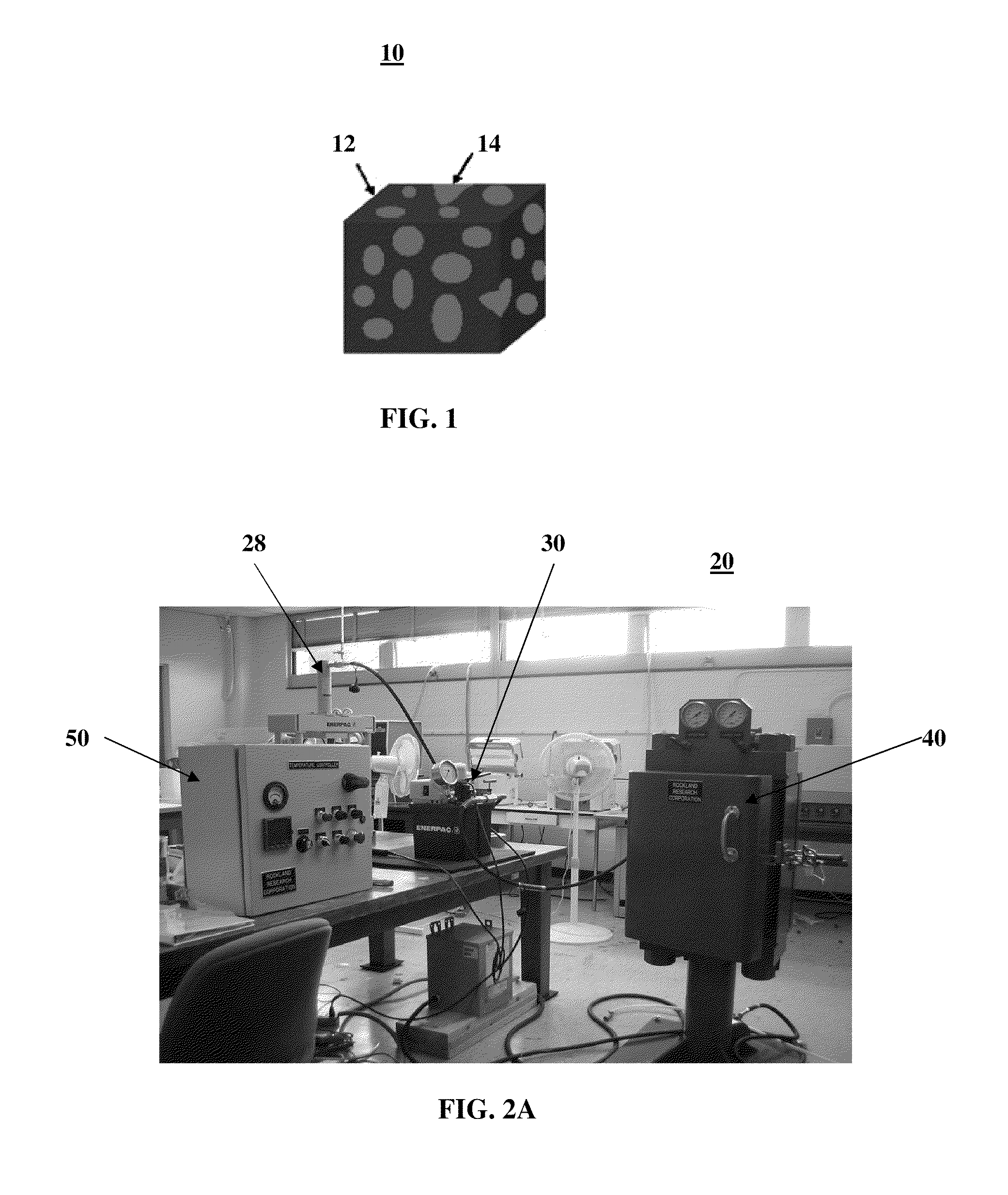
FePt and Fe3O4 Bulk Nanocomposite
[0071]The FePt with face-centered cubic (“fcc”) structure and Fe3O4 nanoparticles are mixed at a mass ratio of 8:1 in a solution before centrifugation, as disclosed in Rong et al. “Bulk FePt-based nanocomposite magnets with enhanced exchange coupling”, J. Applied Physics, 101: 023908, (2007), herein incorporated by reference. The dried nanoparticles are heated before compacting under an Argon atmosphere at 350° C. for 1 hr. to remove surfactants. The powders are then compacted with a warm-compaction press under pressure of 0.5 to 6 GPa for a period of time and at a temperature. In one embodiment, the pressure is 2.5 or 3.8 GPa for 10 min. at temperatures ranging from room temperature (about 20° C.) to 600° C. The obtained bulk samples have dimensions φ6 mm×1.5 mm and φ3 mm×1.2 mm for the compaction pressures of 2.5 and 3.8 GPa, respectively. For comparison, 15 nm Ll0 FePt nanoparticles prepared by the salt-matrix annealing technique were compacted at...
example 2
SmCO5 / Fe, NdFeB, and SmCo / Fe Bulk Nanocomposites
[0087]FIG. 21 shows the comparison of the dependence of density on the compaction temperature for (a) fcc FePt nanoparticles under 2.5 GPa; (b) fcc FePt nanoparticles under 3.8 GPa; (c) Ll0 FePt nanoparticles; (d) MQ-ribbons; (e) crystallized SmCO5 / Fe nanocomposite powders; (f) amorphous SmCo / Fe powders. MQ-ribbons are NdFeB ribbons obtained by rapid quench plus a crushing process. NdFeB ribbons are compacted at different temperatures under 2.5 GPa. The size of the compacts is about φ=6 mm and h=2 mm. The density can reach 100% at 500-600° C., as shown in FIG. 21. The XRD patterns of the starting ribbons and 500° C.-compacted samples that are quite similar. However, the change of grain size may be determined by a very sensitive XRD machine. Hysteresis loops are also similar for different compaction temperatures. For the ideal SmCo / Fe composite, (BH)max=65 MGOe. For the ideal Sm2Fe17Nx.FeCo composite, (BH)max=120 MGOe.
[0088]FIG. 22A is ...
example 3
Deformation in Nanocrystalline Metals
[0096]Nanoparticle deformation mechanism and interface atom diffusion may optimize warm compacting parameters. Utilization of parallel computing programs and Atomistic Computer Simulations may detect increased deformation at and through grain boundaries to increase the bulk nanocomposite produced by the warm compaction method, as disclosed in Swygenhoven et al., “Deformation in Nanocrystalline Metals”; Mats. Today; 9; 5 2006, 24-31, herein incorporated by reference. Increased deformation at and through the grain boundaries will increase the density and the magnetization of the compacts.
PUM
| Property | Measurement | Unit |
|---|---|---|
| Size distribution | aaaaa | aaaaa |
| Temperature | aaaaa | aaaaa |
| Temperature | aaaaa | aaaaa |
Abstract
Description
Claims
Application Information