Image guided intervention

a technology of image guided intervention and guide wire, which is applied in the field of image guided intervention, can solve the problems of unreliable and slow bi-plane fluoroscopy, unreliable guide wire, and greater difficulty of surgeons in guiding the elongated guide wire through the occluded area,

Inactive Publication Date: 2010-03-04
IMRIS
View PDF19 Cites 36 Cited by
  • Summary
  • Abstract
  • Description
  • Claims
  • Application Information

AI Technical Summary

Benefits of technology

[0039]Alternatively the imaging system can be a Magnetic Resonance Imaging system arranged to effect in an initial step a Magnetic Resonance Angiography. In this arrangement preferably the Magnetic Resonance Imaging system includes a magnet which is movable away from a patient support so as to be spaced away from the patient during the guiding. In this way the guiding is effected wholly by the optical fiber system without the mag...

Problems solved by technology

While bypass surgery can provide dramatic relief, it involves major open chest surgery and typically a long period of convalescence.
In those instances where the artery is occluded, the surgeon may have greater difficulty in guiding the elongated guide wire through the occluded area.
Thus, without some type of guidance system, the elongate guide member might undesirably impinge on and possibly perforate or otherwise damage the artery wall.
However, bi-pla...

Method used


Image

  • Image guided intervention
  • Image guided intervention
  • Image guided intervention

Examples


Embodiment Construction

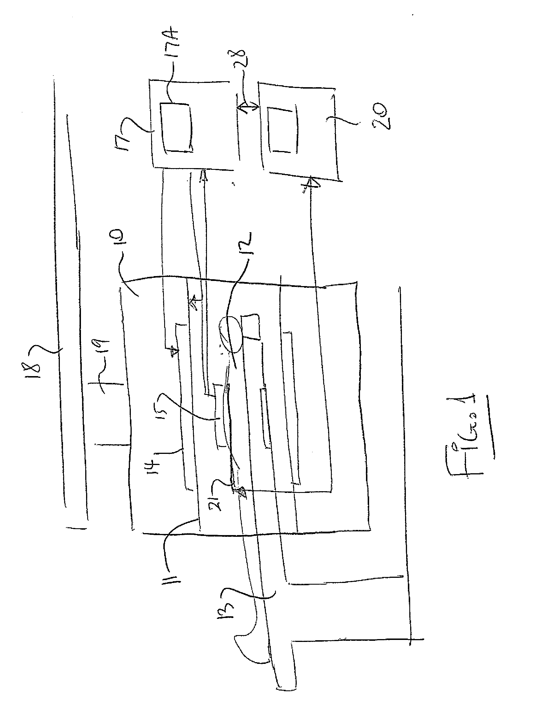
[0067]In FIG. 1 is shown schematically a magnetic resonance imaging system which includes a magnet 10 having a bore 11 into which a patient 12 can be inserted on a patient table 13. The system further includes an RF transmit body coil 14 which generates a RF field within the bore.

[0068]The system further includes a receive coil system generally indicated at 15 which is located at the isocenter within the bore and receives signals generated from the human body in conventional manner. A RF control system 17 acts to control the transmit body coil 14 and to receive the signals from the receive coil 15. The magnet is carried on a rail system 18 by a support 19 so that the magnet and associated operating components can be moved into place at the patient on the table and can be removed to allow the surgeon to carry out the necessary actions on the patient.

[0069]Further details of this arrangement are described in the above U.S. Pat. No. 5,735,278 (Hoult et al) and the above PCT Application...


PUM


Abstract

Image guidance on a computer screen in the patient's vascular system with reduced use of toxic contrast agent and X-ray radiation is obtained by providing anatomical and functional images obtained preferably from an MR Imaging system. A fibre optic device which uses strain measurement to provide an image of the shape and location of the fiber is used to provide spatial information of the elongate guide member as it is pushed through the vascular system with this spatial information being registered to the image of the vascular system by registering the location of the fiber/guide in the image prior to insertion using markers visible in the MR image.

Description

[0001]This invention relates to a method for use in guiding a treatment device from an insertion site to a treatment site in a patient.BACKGROUND OF THE INVENTION[0002]A number of procedures have been suggested in the past for treating disease conditions involving the narrowing or obstruction of the lumen of an artery. This condition, generally referred to as a lesion, is found in patients suffering from atherosclerosis, and can manifest itself as partial or total. The occlusions can be found at various locations in the arterial system, including the aorta, the coronary arteries, the carotid arteries and the peripheral arteries.[0003]In the past, coronary artery occlusions have traditionally been treated by performing coronary bypass surgery, wherein in most cases, a segment of the patient's saphenous vein is taken from the patient's leg and is grafted onto the affected artery at points upstream and downstream of the occluded segment. While bypass surgery can provide dramatic relief...

Claims


Application Information

Patent Timeline
IPC IPC(8): A61B5/05
CPCA61B5/055A61B6/032A61B6/12A61B8/0833G06T2207/20096A61B2019/5251A61B2019/5255G06T2200/24A61B19/5244A61B2034/2055A61B34/20A61B2034/2051
Inventor SAUNDERS, JOHN K.DAHAN, MEIREDE, MAURICIOROBBINS, STEVEN
Owner IMRIS
Why Eureka
Try Eureka