Physical quantity detection circuit and physical quantity sensor device

a detection circuit and sensor technology, applied in the direction of fluid pressure measurement by mechanical elements, electric unknown time interval measurement, setting time indication, etc., can solve the problems of increasing circuit scale and power consumption, and achieve the effect of suppressing the increase in sampling frequency and improving the precision of phase adjustmen

Active Publication Date: 2010-03-04
PANASONIC CORP
View PDF12 Cites 6 Cited by
  • Summary
  • Abstract
  • Description
  • Claims
  • Application Information

AI Technical Summary

Benefits of technology

[0012]According to another aspect of the present invention, the physical quantity detection method is a method for detecting a physical quantity based on a sensor signal from a physical quantity sensor that senses a physical quantity given externally, including the steps of: adjusting the phase of a sampling clock having a predetermined sampling frequency; converting the sensor signal to a digital sensor signal in synchronization with the phase-adjusted sampling clock; and detecting the physical quantity based on the digital sensor signal. In this physical quantity detection method, by adjusting the phase of the sampling clock, the sampling points can be shifted, and as a result, the phase of the digital sensor signal can be changed. Hence, it is possible to improve the precision of the phase adjustment while suppressing increase in sampling frequency.

Problems solved by technology

However, a higher sampling frequency will increase the circuit scale and the power consumption.

Method used


Image

  • Physical quantity detection circuit and physical quantity sensor device
  • Physical quantity detection circuit and physical quantity sensor device
  • Physical quantity detection circuit and physical quantity sensor device

Examples


embodiment 1

Alteration of Embodiment 1

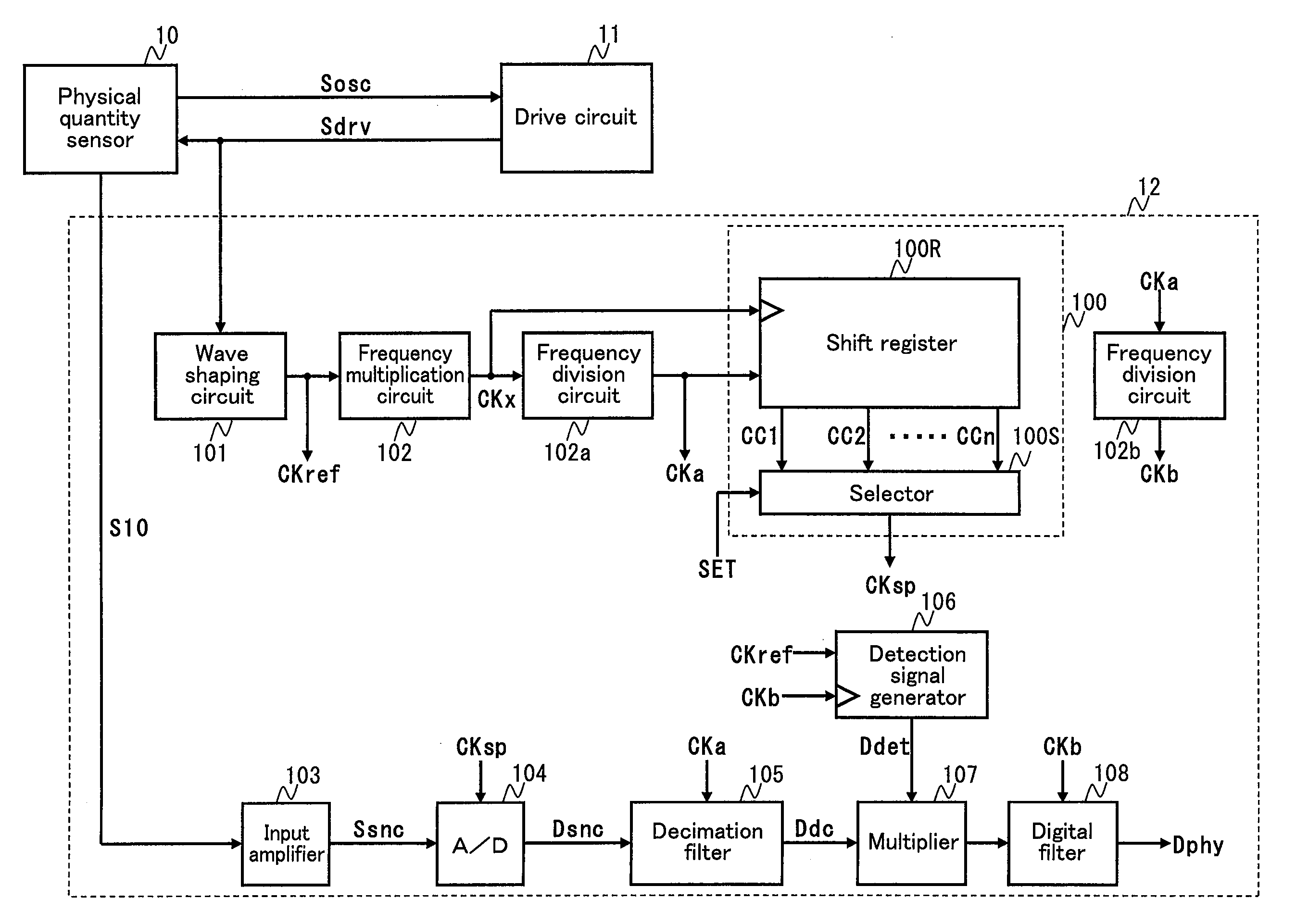
[0055]As shown in FIG. 6, the detection signal generator 106 and the digital filter 108 may operate in synchronization with the sampling clock CKsp as does the analog-to-digital converter 104. A physical quantity detection circuit 12a shown in FIG. 6 includes neither the frequency division circuit 102b nor the decimation filter 105 shown in FIG. 1. As shown in FIG. 7, the detection signal generator 106 starts outputting the sine wave data units D0, D1, D2, . . . synchronizing with the sampling clock CKsp in response to a transition of the reference clock CKref. The multiplier 107 multiplies the digital values P0, P1, P2, . . . from the analog-to-digital converter 104 by the sine wave data units D0, D1, D2, . . . from the detection signal generator 106, respectively. In this case of using the sampling clock CKsp as the operation clock for the physical quantity detection circuit 12a, also, effects similar to those in the case of FIG. 1 can be obtained.

embodiment 2

[0056]FIG. 8 shows an example configuration of a physical quantity sensor device of Embodiment 2. This physical quantity sensor device includes a physical quantity detection circuit 22 in place of the physical quantity detection circuit 12 shown in FIG. 1. The physical quantity detection circuit 22 includes a sampling phase adjustment circuit 200 in place of the sampling phase adjustment circuit 100 shown in FIG. 1. The other configuration is similar to that in FIG. 1.

[0057]The sampling phase adjustment circuit 200 includes a sampling phase adjustment counter 201 and a frequency division circuit 202 (clock generation circuit). The sampling phase adjustment counter 201 starts counting the number of generated pulses of the amplified clock CKx in response to a transition edge of the reference clock CKref, and outputs a timing signal STR once the number of generated pulses reaches a predetermined value SET set under external control. The frequency division circuit 202 starts frequency d...

embodiment 3

Alteration of Embodiment 3

[0076]The sampling phase adjustment circuit 100 shown in FIG. 10 may be replaced with the sampling phase adjustment circuit 200 shown in FIG. 8 as in a physical quantity detection circuit 32a shown in FIG. 15. In this case, also, effects similar to those in the case of FIG. 10 can be obtained.

Other Embodiments

[0077]The physical quantity sensor 10 in the above embodiments does not have to be of the tuning fork type, but may be of a circular cylinder type, a regular triangular prism type, a square prism type, or a ring type, or may be of another shape. Otherwise, as shown in FIG. 16, the physical quantity sensor 10 may be a capacitive acceleration sensor. In this case, the physical quantity sensor 10 includes a fixed portion 10b, a movable portion 10c, movable electrodes Pma and Pmb, detection electrodes Pfa and Nb, and a differential amplifier 10d. The movable portion 10c is connected to the fixed portion 10b so that it can be displaced according to accelera...


PUM

PropertyMeasurementUnit
physical quantityaaaaaaaaaa
sampling frequencyaaaaaaaaaa
frequencyaaaaaaaaaa

Abstract

A physical quantity detection circuit (12) is used for a physical quantity sensor (10) that outputs a sensor signal according to a physical quantity given externally. A sampling phase adjustment circuit (100) adjusts the phase of a sampling clock (CKa). An analog-to-digital converter circuit (104) converts the sensor signal (Ssnc) to a digital sensor signal (Dsnc) in synchronization with the sampling clock (CKsp) phase-adjusted by the sampling phase adjustment circuit. A detection circuit (107) detects the physical quantity based on the digital sensor signal (Dsnc) from the analog-to-digital converter circuit.

Description

CROSS-REFERENCE TO RELATED APPLICATIONS[0001]This is a continuation of PCT International Application PCT / JP2009 / 000305 filed on Jan. 27, 2009, which claims priority to Japanese Patent Application No. 2008-098694 filed on Apr. 4, 2008. The disclosures of these applications including the specifications, the drawings, and the claims are hereby incorporated by reference in its entirety.BACKGROUND OF THE INVENTION[0002]The technique disclosed herein relates to a physical quantity detection circuit used for a physical quantity sensor that detects a physical quantity given externally and to a physical quantity sensor device provided with the same, and more particularly, to a technique of adjusting the phase relationship between a sensor signal and a detection signal.[0003]Conventionally, physical quantity sensor devices capable of detecting a physical quantity (e.g., an angular velocity, an acceleration, etc.) are used in a variety of technical fields such as detection of shake of a digita...

Claims


Application Information

Patent Timeline
Patent Type & Authority Applications(United States)
IPC IPC(8): G06F19/00G01N29/00G01C19/56G01C19/5614G01C19/5776G01P15/125
CPCG01P15/125G01C19/5607G01P2015/0828
Inventor INUKAI, FUMIHITOMUROYA, SEIICHIKAINO, YOICHI
Owner PANASONIC CORP
Why Eureka
Try Eureka