Voltage-controlled oscillator

Active Publication Date: 2010-03-11
NATIONAL CHIAO TUNG UNIVERSITY
View PDF4 Cites 7 Cited by
  • Summary
  • Abstract
  • Description
  • Claims
  • Application Information

AI Technical Summary

Benefits of technology

[0009]As described above, a voltage-controlled oscillator using a variable inductor according to the present invention may have one or more of the following advantages:
[0010](1) The present invention

Problems solved by technology

However, when the required oscillation frequency is increased to some extent (e.g. 60 GHz), due to the reduction in the quality factor (Q) of the variable capacitor, the maximum variable capacitance value tolerated by the same negative impedance circuit is significantly reduced, thus narrowing the adjustable frequency

Method used


Image

  • Voltage-controlled oscillator
  • Voltage-controlled oscillator
  • Voltage-controlled oscillator

Examples


Embodiment Construction

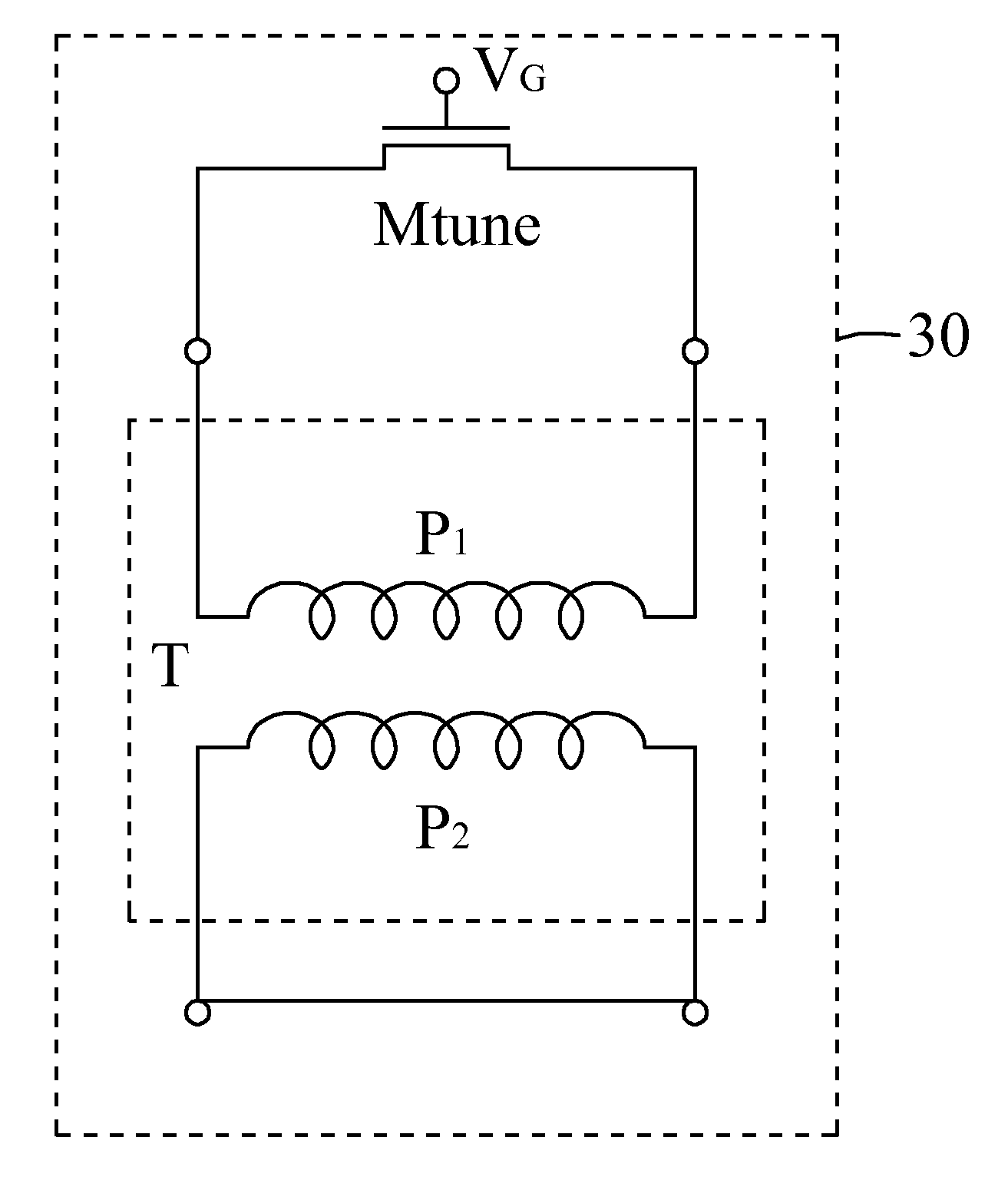
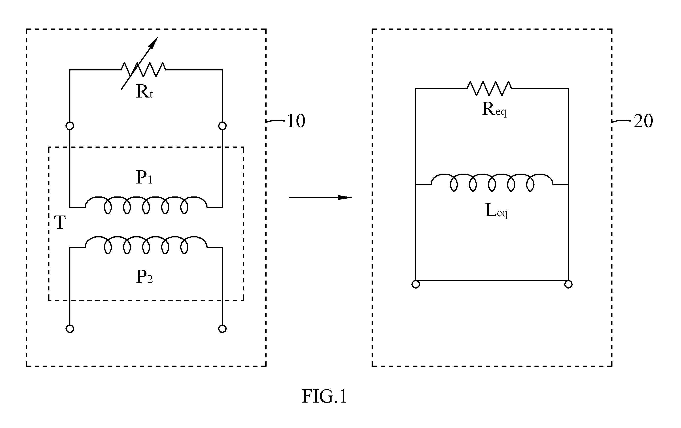
[0022]Referring to FIG. 1, there is illustrated a schematic view showing the structure of using a transformer and a variable resistor to serve as a variable inductor according to an embodiment of the present invention. In this drawing, the variable inductor 10 comprises a transformer T and a variable resistor Rt, and the transformer T comprises a primary side coil P1 and a secondary side coil P2. As seen from the secondary side coil P2, the variable inductor 10 can be equivalent to an equivalent circuit 20, and its equivalent resistance Req and equivalent inductance Leq can be calculated as:

Leq=Rt2L12+ω2L12L22(1-k2)2Rt2L1+ω2L1L22(1-k2)Req=RtL1k2L2+ω2L1L2(1-k2)2k2Rt

[0023]Wherein ω is a frequency, k is a coupling parameter of the transformer T, L1 is the inductance value of the primary side coil P1, and L2 is the inductance value of the secondary side coil P2.

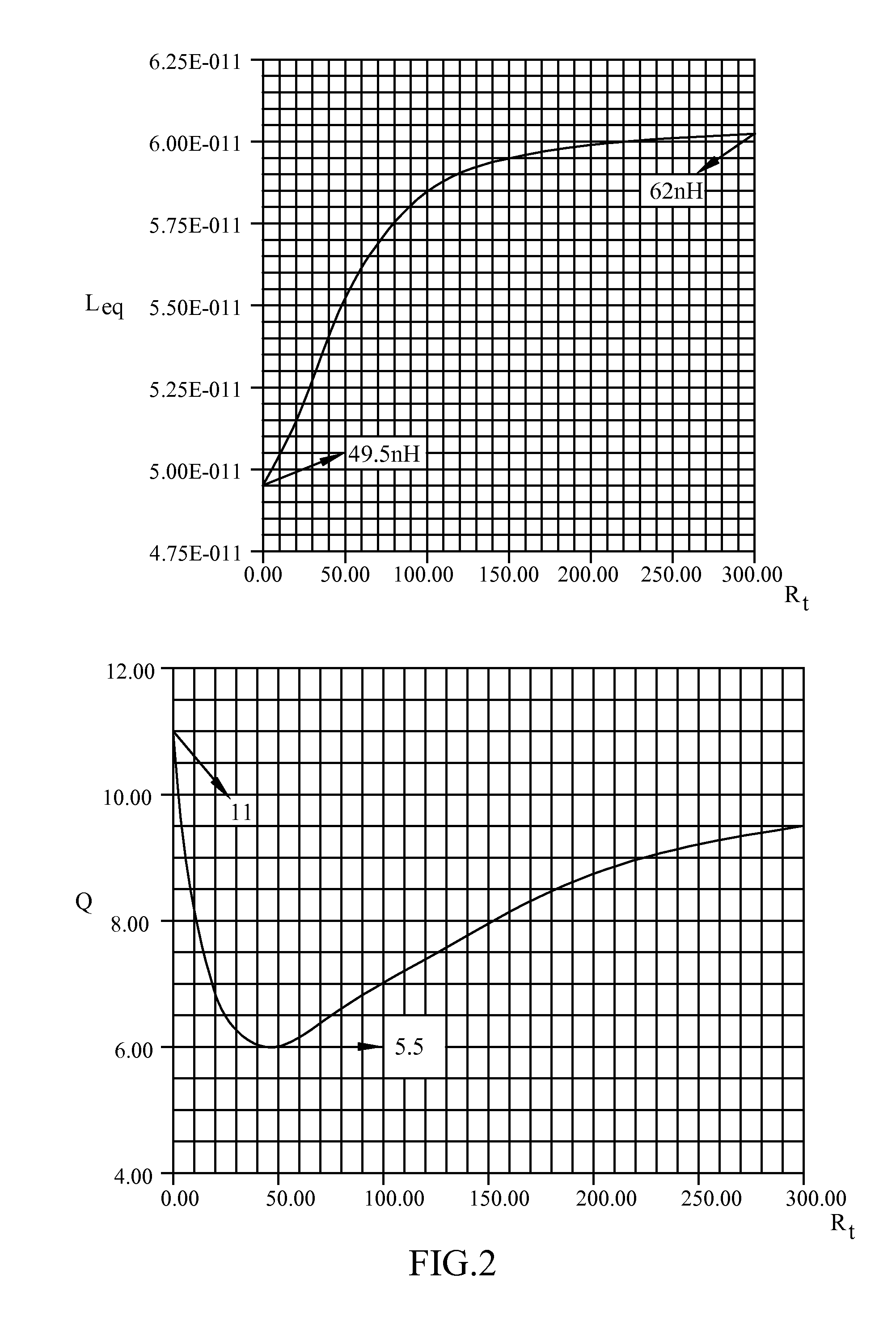
[0024]It can be seen from the above equations that the equivalent inductance Leq changes as the variable resistance Rt changes....


PUM


Abstract

A voltage-controlled oscillator comprises a variable inductor, a negative impedance circuit, an operating voltage source and a ground point. The variable inductor comprises a transformer and a transistor switch, the transformer comprising a primary side coil and a secondary side coil, the primary side coil comprising a first coil and a second coil, and the secondary side coil comprising a third coil and a fourth coil. The transistor switch is connected in parallel with the primary side coil to adjust an inductance value of the variable inductor based on a gate voltage. The negative impedance circuit is connected in parallel with the secondary side coil to compensate the power consumption of the voltage-controlled oscillator during oscillation. The operating voltage source is electrically connected between the third coil and the fourth coil, and the ground point is electrically connected between the first coil and the second coil.

Description

BACKGROUND OF THE INVENTION[0001](a) Field of the Invention[0002]The present invention relates to a voltage-controlled oscillator, and more particularly to a voltage-controlled oscillator using a variable inductor.[0003](b) Description of the Prior Art[0004]A voltage-controlled oscillator (VCO) is an electronic oscillation circuit whose oscillation frequency is controlled by the voltage input. Its oscillation frequency varies with different input DC voltages, and it is often applied to such as frequency modulation (FM) circuits, phase modulation (PM) circuits, or pulse width modulation (PWM) circuits, or the like. An LC resonant circuit comprised of a variable capacitance diode C and an inductor L is usually employed to adjust the oscillation frequency of the high-frequency voltage-controlled oscillator. For instance, increasing the reverse bias voltage of the variable capacitance diode enlarges the depletion region in the variable capacitance diode, thereby further increasing the d...

Claims


Application Information

Patent Timeline
IPC IPC(8): H03K3/01
CPCH03K3/354H03B5/1228H03B5/1293H03B5/1296H03B5/1212
Inventor CHEN, WEI-ZENWU, CHUNG-YUYU, CHI-YAO
Owner NATIONAL CHIAO TUNG UNIVERSITY
Why Eureka
Try Eureka