Dual-frequency antenna

Inactive Publication Date: 2010-03-11
ADVANCED CONNECTEK INC
View PDF4 Cites 56 Cited by
  • Summary
  • Abstract
  • Description
  • Claims
  • Application Information

AI Technical Summary

Benefits of technology

[0009]Another objective of the present invention is to provide a dual-frequency antenna, wherein the radiation conductor thereof has a simple structure and is exempted from too much bending or machining in fabrication, whereby the assembling time is shortened and the yield is promoted, and whereby the present invention is easy to integrate with various wireless communication devices.
[0010]

Problems solved by technology

However, structure miniaturization usually degrades the performance thereof.
Because of intrinsic physical characteristics of an antenna, antenna miniaturization usually results in insufficient gain and inferior bandwidth.
However, the design of two radiation paths has a more

Method used


Image

  • Dual-frequency antenna
  • Dual-frequency antenna
  • Dual-frequency antenna

Examples


first embodiment

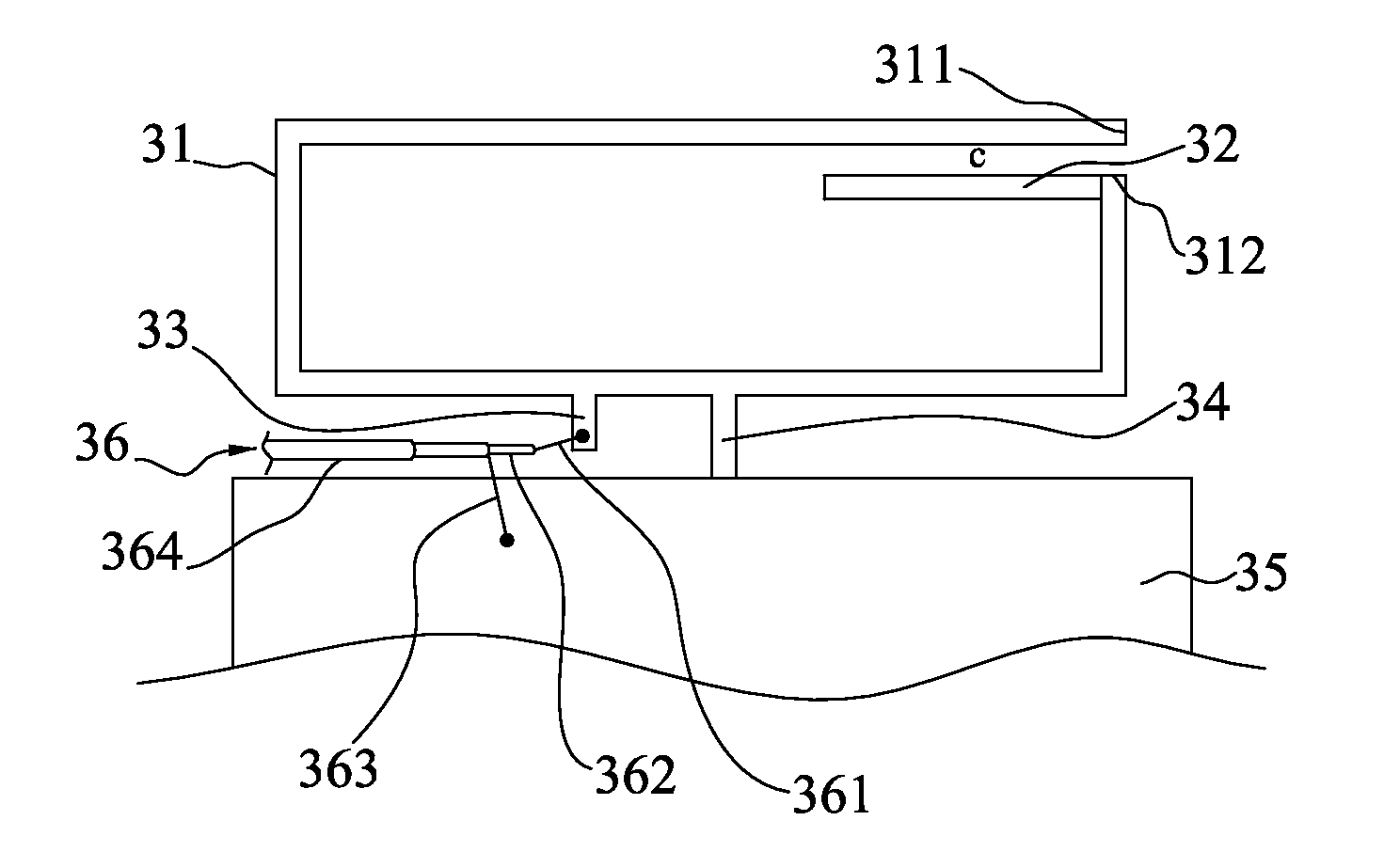
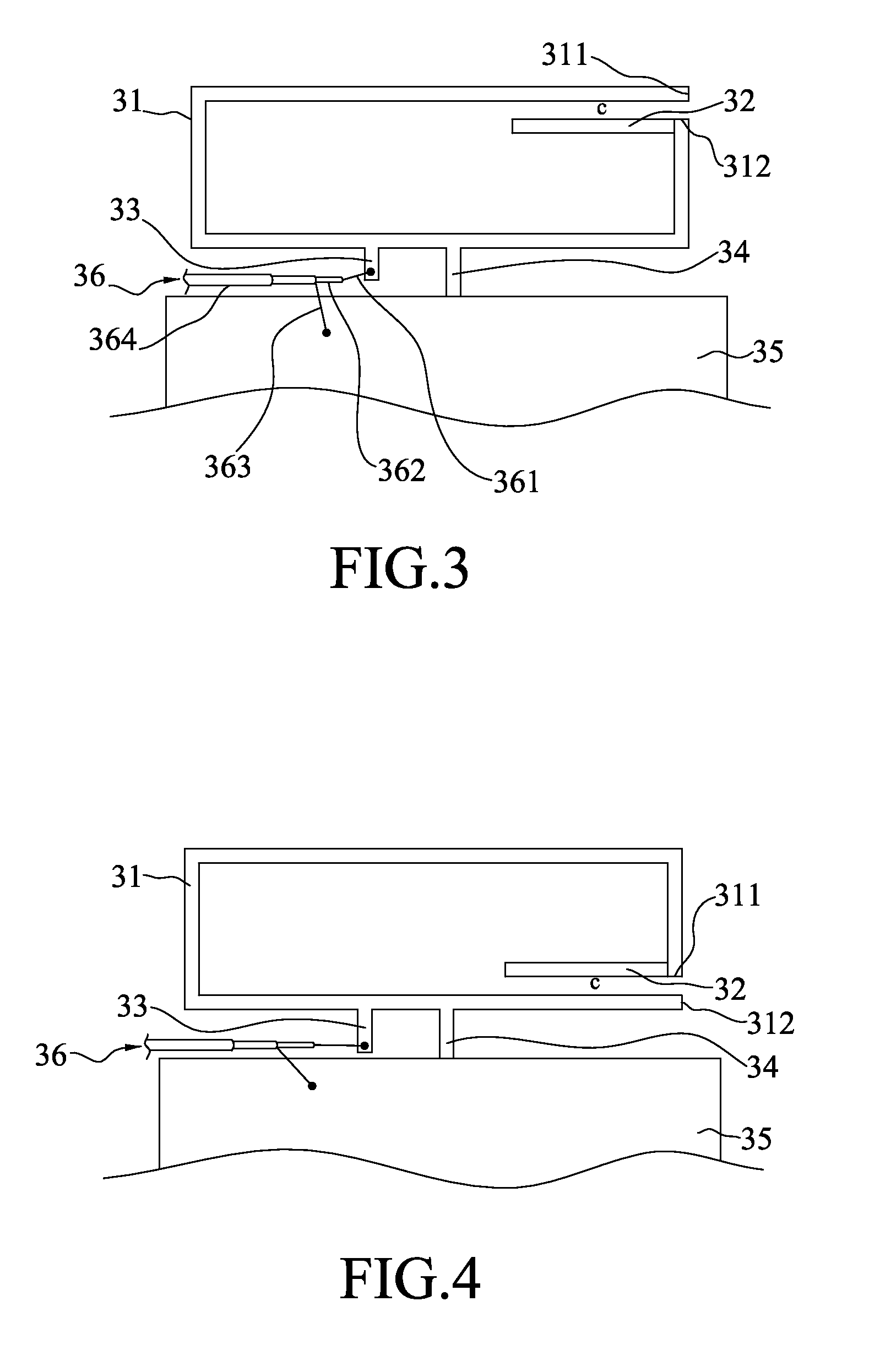
[0023]Referring to FIG. 3, a top view schematically shows the present invention. The dual-frequency antenna of the present invention comprises a radiation conductor 31, an extension conductor 32, a feeder member 33, a short-circuit member 34, a ground plane 35, and a feeder cable 36. The radiation conductor 31 has a first terminal 311 and a second terminal 312. The feeder cable 36 further comprises a central wire 361, an insulating layer 362, an outer wire 363 and a coating 364 in sequence.

[0024]The radiation conductor 31 resembles a C shape. The first terminal 311 and the second terminal 312 of the radiation conductor 31 are arranged close to each other but do not contact each other. The extension conductor 32 is connected to the second terminal 312 and disposed along the contour of the first terminal 311 to have a gap C between the extension conductor 32 and the first terminal 311, and the gap C generates a capacitive coupling effect to increase the radiation transmission efficien...

second embodiment

[0031]In addition to the low-frequency resonant mode and the first high-frequency resonant mode generated by the radiation conductor 31, the parasitic conductor 37 generates a second high-frequency resonant mode in the second embodiment to increase the transmission bandwidth of the high-frequency frequency band. Thus, the present invention can improve the problem of insufficient bandwidth and inferior matching in the conventional dual-frequency.

[0032]Referring to FIG. 7 a diagram shows VSWR (Voltage Standing Wave Ratio) measurement results of the dual-frequency antenna according to the second embodiment of the present invention. When a bandwidth S3 and a bandwidth S4 are defined by a voltage standing wave ratio of 2.5, the bandwidth S3 ranges from 800 MHz to 960 MHz, which covers the AMPS system (824-894 MHz) and GSM system (880-960 MHz), and the operation frequency of the bandwidth S4 ranges between 1400 and 2600 MHz, and the frequency band covers the GPS system (1575 MHz), DCS sys...


PUM


Abstract

The present invention discloses a dual-frequency antenna, which comprises a radiation conductor, an extension conductor, a feeder member, a short-circuit member, and a ground plane. The radiation conductor has a first terminal and a second terminal, which are arranged close to each other but do not contact each other. The extension conductor is connected to the second terminal and disposed along the contour of the first terminal to have a gap between the extension conductor and the first terminal. The feeder member is connected to the radiation conductor. One end of the short-circuit member is connected to the radiation conductor, and the other end is connected to the ground plane. The radiation conductor generates a low-frequency resonant mode and a first high-frequency resonant mode. In the present invention, a single radiation conductor generates two resonant modes to form the operational frequency bands of the dual-frequency antenna.

Description

BACKGROUND OF THE INVENTION[0001]1. Field of the Invention[0002]The present invention relates to a dual-frequency antenna, particularly to an antenna structure, which uses a single radiation conductor to generate the operational frequency bands of a dual-frequency antenna system.[0003]2. Description of the Related Art[0004]The antenna is an essential element for all wireless communication devices. Recently, it has been a trend to equip wireless communication devices with a small, slim and lightweight antenna. However, structure miniaturization usually degrades the performance thereof. Because of intrinsic physical characteristics of an antenna, antenna miniaturization usually results in insufficient gain and inferior bandwidth. Thus, improving gain and bandwidth becomes an important task in miniaturization of the antenna. A dual-frequency antenna is a type of miniature antenna formed via appropriately layouting radiation elements to generate two resonant frequencies without increasi...

Claims


Application Information

Patent Timeline
IPC IPC(8): H01Q1/38H01Q5/10
CPCH01Q1/243H01Q1/38H01Q5/378H01Q5/357H01Q9/42
Inventor CHIU, TSUNG-WENCHANG, HUNG-CHILEE, WEN-HISHSIAO, FU-REN
Owner ADVANCED CONNECTEK INC
Why Eureka
Try Eureka