Data transmitting method and data transmitting apparatus

a data transmission and data technology, applied in the direction of digital transmission, pulse manipulation, pulse technique, etc., can solve the problems of inability to quickly respond to the signal, disadvantageous decrease in transmission efficiency, increased length of guard interval signal, etc., to improve the transmission channel passage rate of spectrum energy of the transmission signal, improve the snr, and improve the snr

Inactive Publication Date: 2010-03-11
NAT INST OF ADVANCED IND SCI & TECH
View PDF8 Cites 1 Cited by
  • Summary
  • Abstract
  • Description
  • Claims
  • Application Information

AI Technical Summary

Benefits of technology

[0035]In the data transmitting method according to the present invention, the following effect can be achieved.
[0036]At the time of transmission at a low transmission symbol rate, a transmission signal is transmitted by using a wide band, and further, by using a fractionally-spaced equalizer, the equalizer can naturally select a band in good condition from a transmission channel, and the SNR can be improved.
[0037]Also, in the data transmitting apparatus according to the present invention, the following effects can be further achieved.
[0038]Since a correlator is used to shape a transmission spectrum, a transmission channel passage rate of spectrum energy of the transmission signal can be improved.
[0039]Since a precoder is used to control the band selection characteristic of the equalizer, the SNR can be improved.
[0040]In addition, the transmission spectrum can be freely shaped in accordance with required specifications, for example, the setting of the notch frequency.

Problems solved by technology

Furthermore, as another problem in the indoor wiring, not only noise generated from a load but also an interference signal and noise induced by the resonance of the indoor wiring serving as an antenna with an electromagnetic wave in the air are added at a level equivalent to that of the signal power.
In this OFDM transmission scheme, however, if roll-off of a transmission pulse is decreased in order to increase frequency use efficiency, the length of a guard interval signal is increased, and the transmission efficiency is disadvantageously decreased.
Further, since the OFDM transmission scheme is a block transmission scheme, blocks have to be reassembled at the time of fluctuations in the transmission path, and quick response is difficult.
Furthermore, as a generally known technology, when the characteristic of the transmission channel becomes deteriorated, a fallback mode is adopted to decrease a data transmission rate (refer to Japanese Patent Application Laid-Open Publication No. 2000-22771).
Therefore, when the transmission quality is decreased, fallback is performed without considering the spectrum amplitude of the transmission channel.

Method used


Image

  • Data transmitting method and data transmitting apparatus
  • Data transmitting method and data transmitting apparatus
  • Data transmitting method and data transmitting apparatus

Examples


Embodiment Construction

[0053]Embodiments of the present invention will be described below with reference to the drawings.

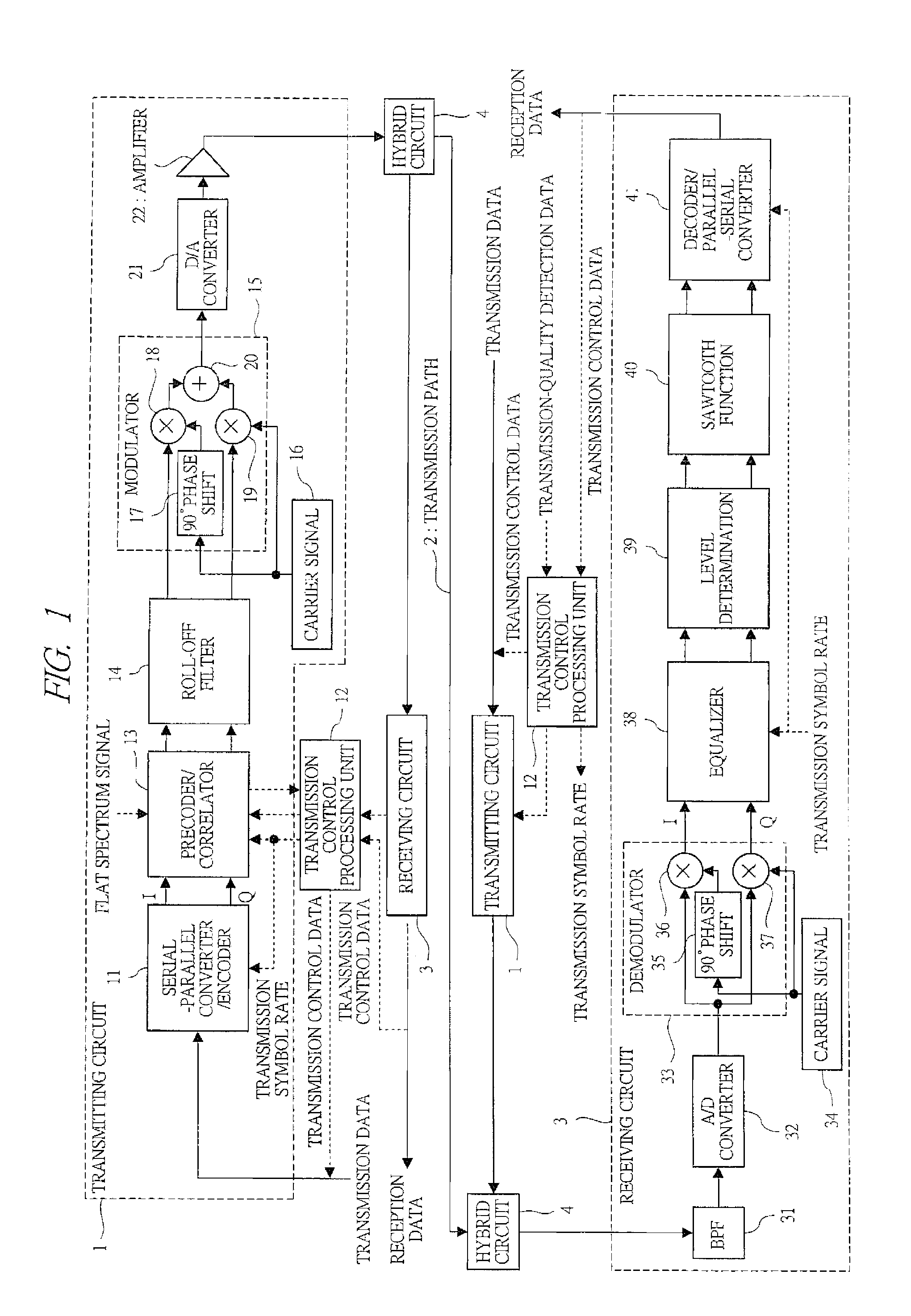
[0054]FIG. 1 is a block diagram showing the entire configuration of a PLC data communication system, which exemplifies a data transmission method according to the present invention. Data transmitting apparatuses (parent MODEM, child MODEM) are connected to both ends of a transmission path 2 (indoor wiring).

[0055]The one data transmitting apparatus (PLC terminal) is shown in an upper portion of FIG. 1, and the other data transmitting apparatus having the same configuration is shown in a lower portion thereof. Each data transmitting apparatus has a transmitting circuit 1 and a receiving circuit 3 connected to the transmission path 2 via a hybrid circuit 4. Details of the transmitting circuit 1 will be described by referring to the data transmitting apparatus in the upper portion, and those of the receiving circuit 3 will be described by referring to the data transmitting apparatus in the ...


PUM


Abstract

A serial-parallel converter/encoder unit 11 inputs a transmission symbol data at a transmission symbol rate that is one-Nth of a base-point symbol rate. A precoder/collator 13 creates a transmission symbol waveform at the base-point symbol rate. The transmission symbol waveform becomes a transmission signal after passing through a roll-off filter 14 with a band corresponding to the base-point symbol rate and a modulator 15. A reception signal demodulated by a demodulator 33 is input to a fractionally-spaced equalizer 38 that operates at the base-point symbol rate and is forcibly equalized at the transmission symbol rate by using a reference signal. A level of a signal output from the fractionally-spaced equalizer 38 at the transmission symbol rate is determined by a level determining unit 39 and becomes a reception symbol data by a sawtooth-function output unit 40.

Description

CROSS REFERENCE TO RELATED APPLICATIONS[0001]This application is entitled to the benefit of and incorporates by reference essential subject matter disclosed in International Patent Application No. PCT / JP2007 / 052451 filed on Feb. 13, 2007; Japanese Patent Application No. 2006-045746 filed Feb. 22, 2006; and Japanese Patent Application No. 2006-117295 filed Apr. 20, 2006.TECHNICAL FIELD[0002]The present invention relates to a data transmitting method and a data transmitting apparatus in which data is transmitted at a reduced transmission symbol rate through a transmission channel with low transmission quality, for example, a transmission channel in which an attenuation band is wide and noise equivalent to signal power is added.BACKGROUND ART[0003]In recent years, PLC (Power Line Communication) data communication system in which a power line for commercial power supply is used to bidirectionally connect between electrical appliances has attracted attention at home or in office.[0004]In...

Claims


Application Information

Patent Timeline
Patent Type & Authority Applications(United States)
IPC IPC(8): H04L27/01H04L27/00
CPCH04L27/38H04L25/03044
Inventor SATO, YOICHIHIGUCHI, TETSUYAMURAKAWA, MASAHIRO
Owner NAT INST OF ADVANCED IND SCI & TECH
Why Eureka
Try Eureka