
Hob cutter with a coating and method for coating hob cutter

Inactive Publication Date: 2010-03-11
FETTE +1
View PDF11 Cites 21 Cited by
  • Summary
  • Abstract
  • Description
  • Claims
  • Application Information

AI Technical Summary

Benefits of technology

[0017]A flexible adjustment of the coating is enabled through the combination according to the invention of layers with different hardness and different internal stresses, which are in turn built from individual nanolayers that also differ in their individual properties. Thus, through the combination according to the invention of a multiplicity of layers and nanolayers, on the one hand, a high resistance to abrasion, and thus, a higher wear resistance is attained through hard, although at the same time, brittle layers. On the other hand, through a high ductility of the relatively softer layers, a sufficient loading capacity for strike or impact stress, such as those that occur specifically with hob cutting, is guaranteed. Thereby the wear resistance of the hob cutter tool is increased, and in particular, the tendency of crack propagation in the coating or the separation of the coating is reduced.
[0030]Hob cutters have a sharp cutting edge for machining. According to a further embodiment of the invention, the cutting edges of the hob cutting tool can be rounded before the application of the coating. Such rounded cutting edges permit better coating. In particular, the adhesion of the coating or the bonding layer, as well as the mechanical stability of the coated cutting edges is improved.

Problems solved by technology

Milling cutters, for example hob cutter tools, are subjected in practice to high stresses.
As a result, there is comparatively high wear.
Hob cutter tools, in particular, are subject to strong strike or impact stresses during operation.
There is a conflict of goals in that on the one hand the hardest possible coatings are desired for the wear resistance, however, such hard layers can absorb mechanical stress peaks only to a small degree.
Through this, cracks can propagate through the tool coating, and lead to tool failure.
The known coatings have in common that they do not always possess optimal properties with regard to their wear resistance on the one hand, and their sensitivity to strike or impact stress on the other.
The removal of swarf from a workpiece being processed represents another problem.
However, this represents an additional work step and gives rise to corresponding costs.
However, due to the constant composition of the target, the flexibility with regard to the possible composition of layers that can be deposited is limited.
With highly stressed tools, such as hob cutters, the coating loses its function due to wear after a certain service life.
However, the surface areas not removed in the process, have sometimes been subjected to very high temperatures in the prior use of the tool.
Due to the change effected thereby of these areas, this leads to an at least partially insufficient adhesion of the new coating.
This in turn, leads to the fact that the coating can fail during operation, for example, detach.
Due to this problem also, the number of possible recoatings is limited.

Method used


Image

  • Hob cutter with a coating and method for coating hob cutter
  • Hob cutter with a coating and method for coating hob cutter
  • Hob cutter with a coating and method for coating hob cutter

Examples


Embodiment Construction

[0039]While this invention may be embodied in many different forms, there are described in detail herein a specific preferred embodiment of the invention. This description is an exemplification of the principles of the invention and is not intended to limit the invention to the particular embodiment illustrated

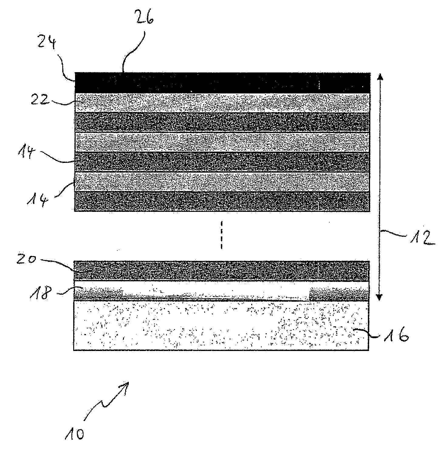
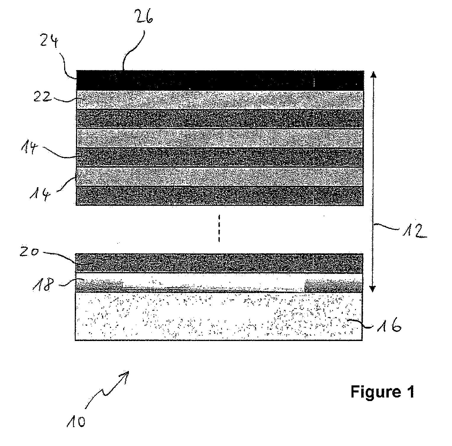
[0040]In FIG. 1, a hob cutter tool 10 according to the invention is represented schematically and in section. The hob cutter tool 10 has a coating 12 composed of a multiplicity of layers 14 arranged on top of each other. First, a bonding layer 18, here a CrN layer 18, is applied onto tool base body 16. The bonding layer 18 improves the adhesion of the remaining layers and at the same time has an impact absorbing effect. A first AlCr nitride layer 20 is applied onto the bonding layer 18. The first AlCr nitride layer is from a first layer type and has a first Al:Cr ratio in the range of 60:40 to 65:35. A second AlCr nitride layer, not represented more closely in FIG. 1, of a sec...


PUM

PropertyMeasurementUnit
Percent by atomaaaaaaaaaa
Pressureaaaaaaaaaa

Abstract

The invention relates to a hob cutter tool with a coating, wherein the coating is produced by a physical vapor deposition method, in which in a coating chamber in an atmosphere containing nitrogen, an arc discharge is generated in each case between at least one anode and at least one pure Al cathode on the one hand, and at least one pure Cr cathode on the other hand, and in this way, Al and Cr are vaporized from the cathode, in which the hob cutter tool to be coated is rotated in the coating chamber, wherein the tool is subsequently guided past the at least two cathodes, and in which the vaporized Al and Cr is deposited in atomic or ionized form together with nitrogen from the atmosphere containing nitrogen onto the hob cutter tool led rotating past the cathodes. The coating has a multiplicity of layers, composed of (AlCr)-nitride, arranged on top of each other, wherein the multiplicity of layers is formed from two layer types differing with respect to their Al:Cr ratio, wherein a first layer type has an Al:Cr ratio in the range of 55:45 to 65:35, and a second layer type has an Al:Cr ratio in the range of 70:30 to 74:26, and wherein the two layer types alternate with each other in the coating, wherein each of the layers, in turn is formed from a multiplicity of nanolayers arranged on top of each other, and wherein the coating is connected to the tool base body using a bonding layer. Furthermore, the invention relates to a method for recoating such a hob cutter tool.

Description

CROSS-REFERENCE TO RELATED APPLICATIONS[0001]Not applicable.STATEMENT REGARDING FEDERALLY SPONSORED RESEARCH[0002]Not applicable.BACKGROUND OF THE INVENTION[0003]The invention relates to a hob cutter with a coating and a method for coating a hob cutter. Milling cutters, for example hob cutter tools, are subjected in practice to high stresses. As a result, there is comparatively high wear. Hob cutter tools, in particular, are subject to strong strike or impact stresses during operation.[0004]It is known to provide such tools with a coating that is adapted to their application conditions, for example a hard coating. For this, physical vapor phase deposition (PVD) is used. For hobbing and for other cutting work, thus far, mainly single layer coatings, e.g., TiN, TiAlN or AlCrN coatings have been used. With such coatings, there is a constant chemical composition across the thickness. There is a conflict of goals in that on the one hand the hardest possible coatings are desired for the w...

Claims


Application Information

Patent Timeline
IPC IPC(8): B23B27/14B32B9/00C23C14/34
CPCB23F21/16C23C14/0641C23C14/325Y10T428/30Y10T428/24975Y10T428/24942C23C30/005Y10T428/31678
Inventor MORSTEIN, MARCUSCSELLE, TIBORLUMKEMANN, ANDREASKOHLSCHEEN, JORN
Owner FETTE
Features
  • Generate Ideas
  • Intellectual Property
  • Life Sciences
  • Materials
  • Tech Scout
  • Unparalleled Data Quality
  • Higher Quality Content
  • 60% Fewer Hallucinations
Learn More