
System for generation of useful electrical energy from isotopic electron emission

Inactive Publication Date: 2010-03-11
WEBER DAVID +1
View PDF44 Cites 7 Cited by
  • Summary
  • Abstract
  • Description
  • Claims
  • Application Information

AI Technical Summary

Benefits of technology

[0017]It is an object of the invention to provide a safe and cost-effective m

Problems solved by technology

However, most such decay is the result of exposure of the nucleus to extreme conditions of heat and exposure to other sub-atomic particles, as often occur during nuclear fission.
In the nucleus of most naturally occurring elements, neutrons cannot decay because there is no available quark orbit for a decaying quark to occupy.
However, when subjected to the high energy and extreme heat of nuclear fission, the d quark does decay, thus rendering the neutron unstable.
One of the primary drawbacks to the use of nuclear power is the radioactive waste which results from its fission process.
Much of the waste of the system is in the form of “spent” fuel rods which cannot efficiently sustain the fission reaction process in the reactor.
There are no final procedures for the storage of spent fuel rods and other radioactive material.
That is, no steps are underway to make use of the massive amount of radioactive decay energy, including beta decay energy, that exists in radioactive materials, especially in spent fuel rods and plutonium by-products.
Other attempts have been made to convert radioactive decay energy to electrical energy, however, none have proved commercially viable due to their complexity, minimal power generating capability, or lack of durability.
The primary deficiency of these devices has been degradation of the structures by long term exposure to the high kinetic energies of the beta electrons.

Method used


Image

  • System for generation of useful electrical energy from isotopic electron emission
  • System for generation of useful electrical energy from isotopic electron emission
  • System for generation of useful electrical energy from isotopic electron emission

Examples


embodiment 600

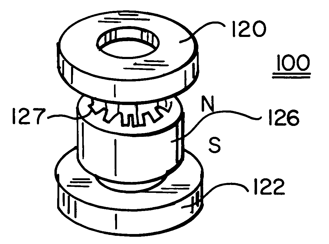
[0072]Shown in FIG. 20 is a further embodiment 600 of the present invention This embodiment, like that of FIG. 19, employs a common anode rod 612 upon which are stacked groups 601 of a lower magnet 620, an anode block 616A, and an opposing magnet 622. Each group 601 is separated from the next successive group by a magnetically insulating layer 623. In this embodiment, as with the other embodiments above described, a dielectric 660 may be inserted within either or both the interaction space of anode block 616A or the anode cavities 627 of the anode block. These dielectrics, wherever positioned, may be tunable, as is known in the art of dielectrics, as taught in U.S. Pat. Nos. 6,774,077 and 7,060,636. The significance of use of a dielectric in the interaction space is that the extreme velocity and momentum of the beta decay electrons may be mediated and more readily adapted in radius of rotation about the cathode within the interaction space to achieve objectives of improved life of t...

embodiment 700

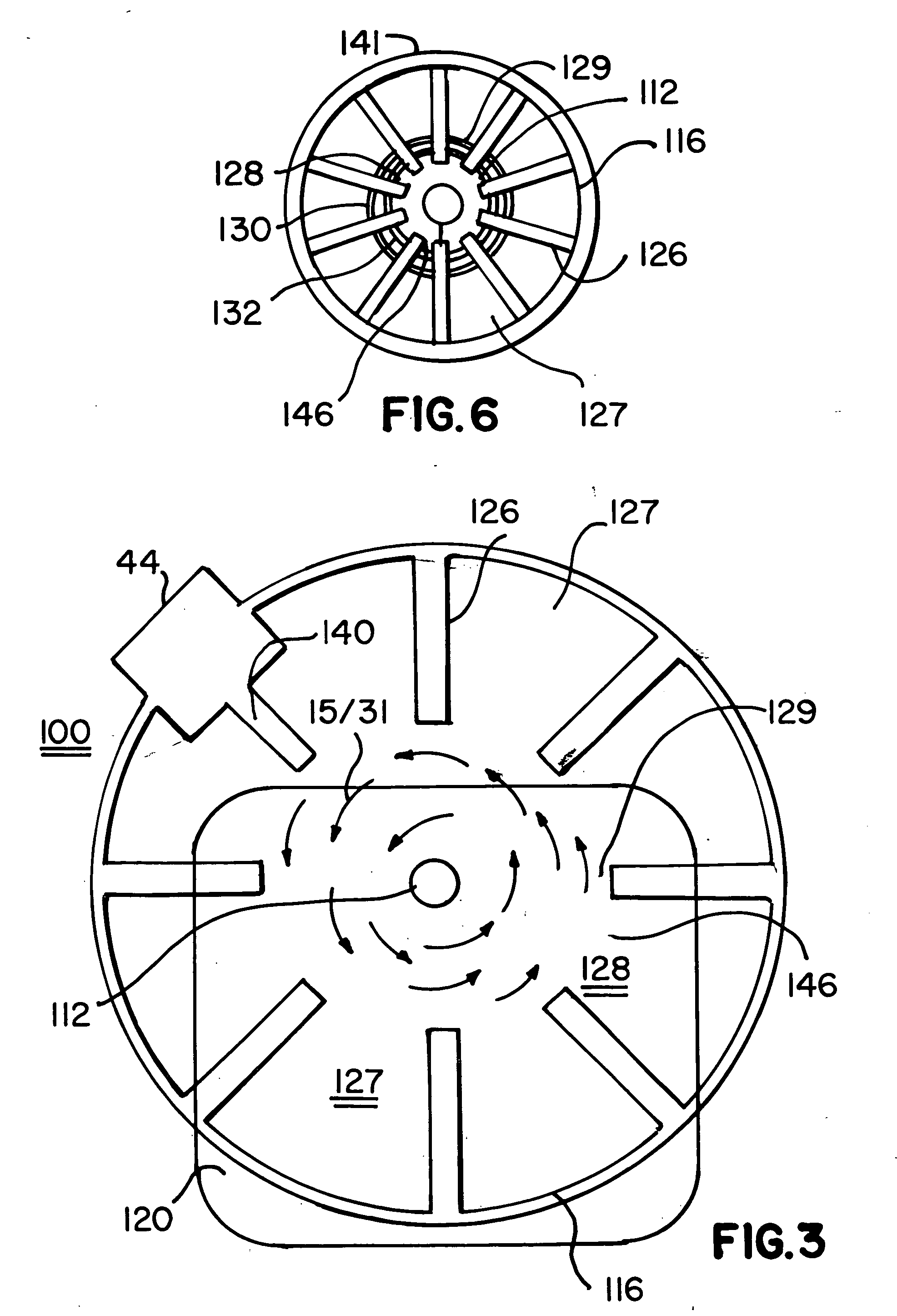
[0076]In FIG. 25 is shown a schematic of a further embodiment 700 of the invention in which a polar array of antennae 727 are used as a functional equivalent of said anode cavities. Therein, a cathode 712 emits beta decay electrons 12 which, as in other embodiments, rotate within an interaction space 728. However, the resultant obtaining electron cloud induces the above-discussed LC values and excitation to antennae 727, as opposed to said cavities 27 / 127 / 227 / 327 of the other embodiments and induces positive and negative polarities. These polarities are strapped together by strapping means 730 and 732. Said antennae will resonate in like fashion to said cavities. Said strapping is used for purposes of phase lock, amplitude control and communication of output 725 to an optional power port, wave guides (not shown), and a power combiner 760.

[0077]It is to be appreciated that the principles of the present invention are equally applicable to use with a cathode characterized by the emissi...


PUM


Abstract

Beta and alpha-ray particles emitted by radio-isotopic by-products of nuclear fission, such as nickel 63, are used as a power source at the cathode of a microwave generating magnetron. Such particles include high speed, high energy electrons having a large EMF associated therewith. In the magnetron, a radial electrical vector, between the cathode and anode, interacts with an axial magnetic vector to produce a cloud of electrons that rotates about the magnetron axis. The speed, geometry and density of the rotating cloud may be modulated by an external RF input or grids within the interaction space of the magnetron. At the periphery of the interaction space is a polar array of anode cavities into which the rotating field induces an LC equivalent parameter that includes high energy microwaves that may be used as an input for the generation of AC or DC power.

Description

CROSS REFERENCE TO RELATED APPLICATION[0001]This application claims the benefit under 35 USC 119(e) of Provisional Patent Application Ser. No. 60 / 737,931, filed Nov. 18, 2005, and the same is incorporated by reference herein in its entirety.BACKGROUND OF THE INVENTION[0002]A. Area of Invention[0003]The use of beta or alpha particles of radio isotopic elements that are typically by-products of nuclear fission are used as a power source for the generation of electricity.[0004]B. Prior Art[0005]Beta particles are a category of electrons emitted from a neutron of an atomic nucleus during its decay. Over a period, known as the isotope half life, a neutron of a decaying nucleus is converted into a proton, increasing by one the atomic number of the nucleus thereby increasing by one step in the periodic table an atom subject to such decay. The decay of the neutron may, in rare circumstances, result from a natural process. However, most such decay is the result of exposure of the nucleus to ...

Claims


Application Information

Patent Timeline
IPC IPC(8): H01M2/00H01M14/00
CPCH01J23/05G21H1/04
Inventor WEBER, DAVIDCOCHRANE, JOHN
Owner WEBER DAVID
Learn More