Method for operating a hybrid drive of a motor vehicle

a hybrid drive and motor vehicle technology, applied in the direction of engine-driven generator propulsion, electric propulsion mounting, transportation and packaging, etc., can solve the problems of degrading the efficiency of the combustion engine, so-called boost operation only temporarily feasible, and high dynamic adjustmen

Active Publication Date: 2010-03-11
ROBERT BOSCH GMBH
View PDF7 Cites 11 Cited by
  • Summary
  • Abstract
  • Description
  • Claims
  • Application Information

AI Technical Summary

Benefits of technology

[0020]In embodiments of the present invention, it is provided that the electrical machine be utilized as a generator and as an electric motor for the hybrid drive. Given a proper use, there is no need for a separate generator to maintain the vehicle electrical system or to charge the electrical accumulator.

Problems solved by technology

This so-called boost operation is only temporarily feasible (over the medium term) since energy is withdrawn from the electrical energy accumulator in the process.
The finite setting speed of the throttle valve actuator and the dynamic charge effects in the intake manifold (airpath) do not permit a highly dynamic adjustment of a predefined air mass flow rate and of the thereby generated combustion engine torque.
However, retarding the ignition timing to a later ignition point degrades the efficiency of the combustion engine and increases the fuel consumption and the exhaust emissions.
The limitation of the operating time of the boost and / or recuperation operation is derived from the duration of a typical acceleration process of a motor vehicle (for example, in the case of a passing maneuver) and from the existing quantity of energy stored in the electrical accumulator.

Method used


Image

  • Method for operating a hybrid drive of a motor vehicle
  • Method for operating a hybrid drive of a motor vehicle
  • Method for operating a hybrid drive of a motor vehicle

Examples


Embodiment Construction

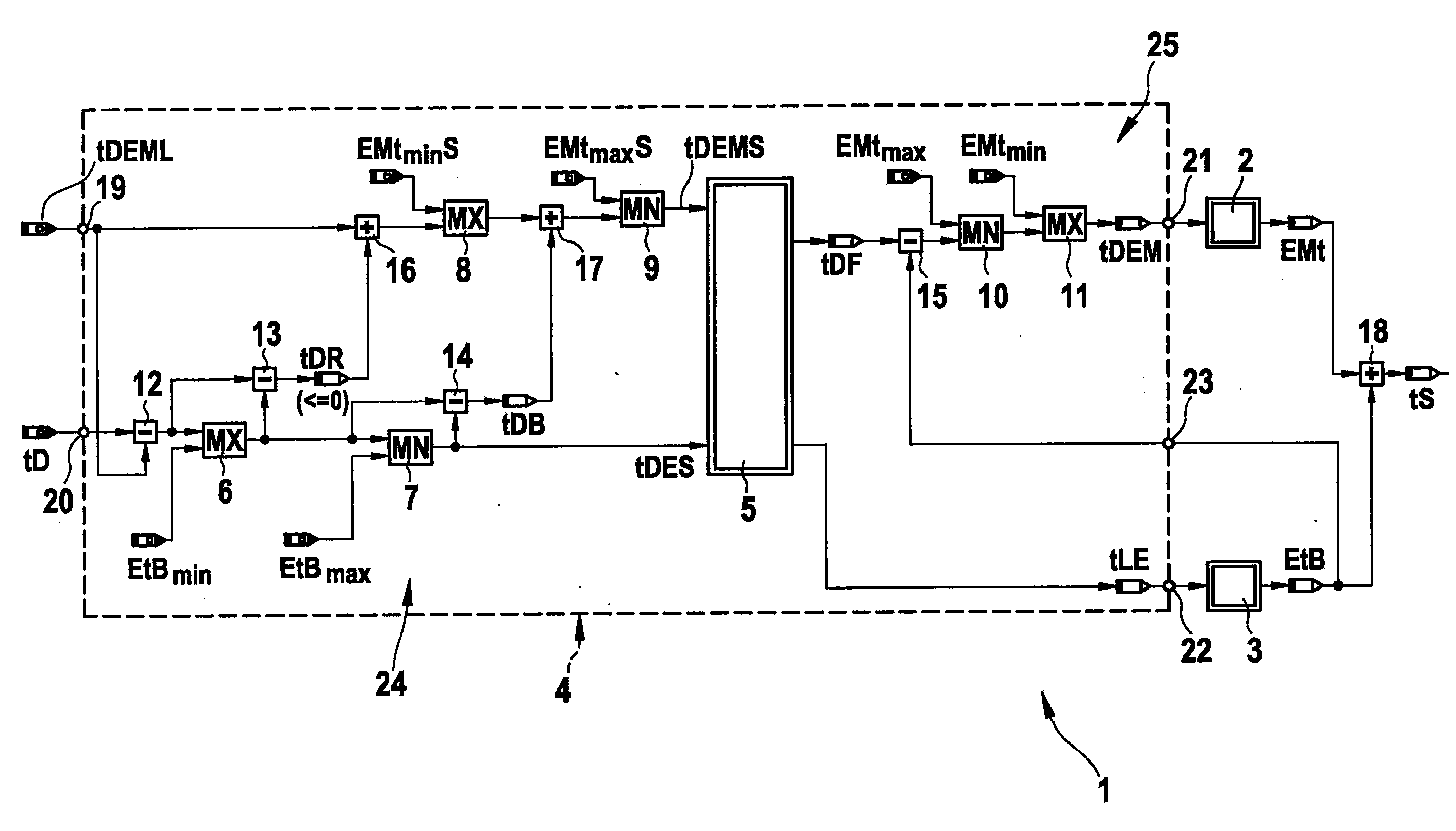
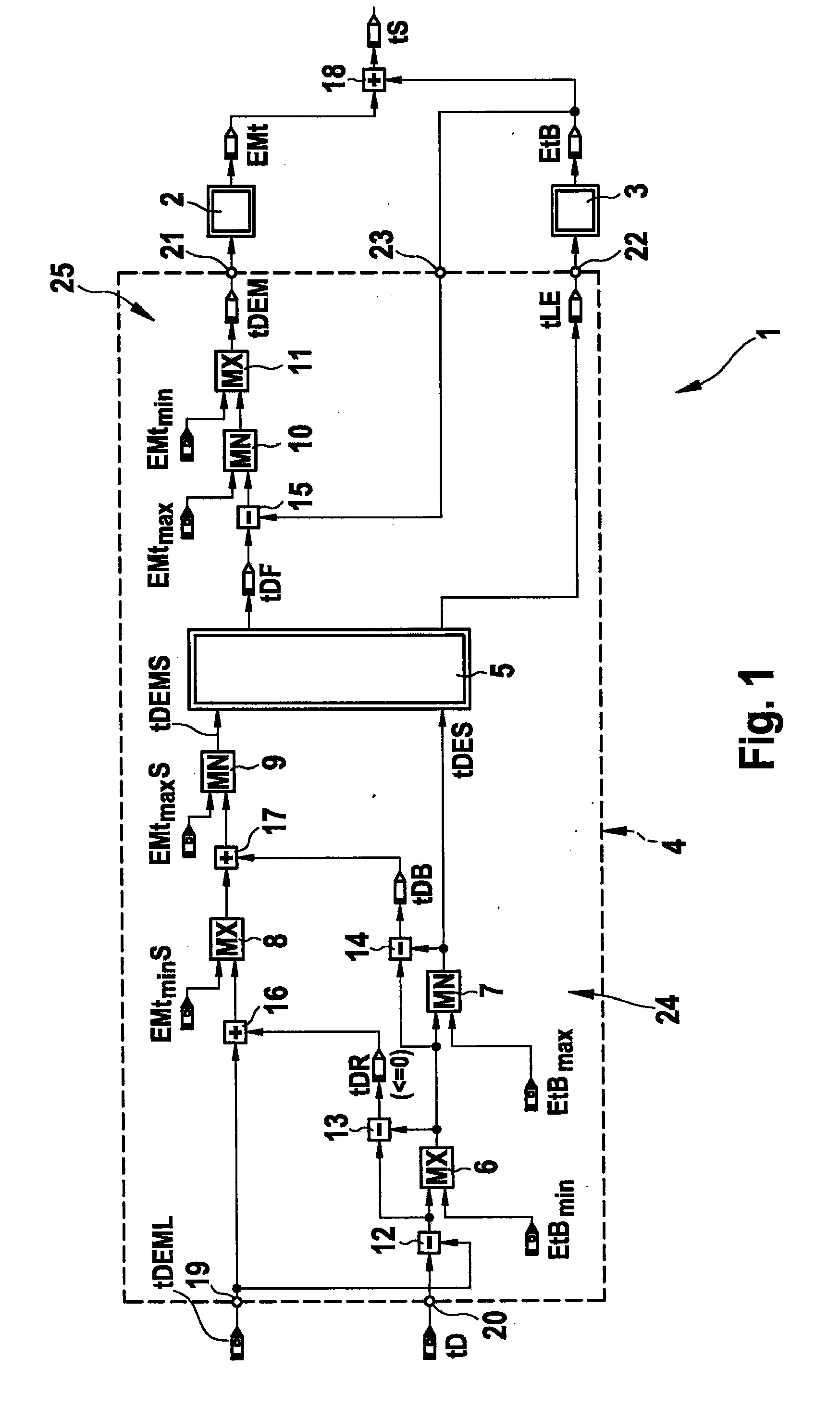
[0024]FIG. 1 shows a block diagram of a simulation of a hybrid drive 1 having two driving motors 2, 3, the first driving motor being designed as an electrical machine 2 and the second driving motor as combustion engine 3. Driving motors 2, 3 are controlled in a coordinated process by a coordinating control device 4 having a ride comfort filter 5, a plurality of comparator units 6, 7, 8, 9, 10, 11, a plurality of subtraction units 12, 13, 14, 15, and a plurality of adder units 16, 17. Comparator units 6, 8, 11 compare two input values and output the higher input value as an output value; comparator units 7, 9, 10 output the lower input value. The actual torques (combustion-engine base torque EtB and electric-machine actual torque EMt) are summed via a transmission 18 to form an output torque (hybrid-drive summed torque) tS. Control device 4 has an input 19 for receiving the signal of a torque selection for the charging strategy used in the operation for maintaining the vehicle electr...


PUM


Abstract

A method is provided for operating a hybrid drive of a motor vehicle which has a combustion engine, at least one electrical machine, and at least one electrical accumulator, the electrical machine and the electrical accumulator belonging to an electrical system of the motor vehicle. The following steps are provided for implementing the method: subdividing the operation of the electrical machine into adjacent subranges of a) transient compensation operation, b) boost and/or recuperation operation, and c) operation for maintaining the vehicle electrical system; assigning torque limits and/or power output limits of the electrical machine in at least two subranges; and, releasing and/or influencing the particular torque limits and/or power output limits of the subranges as a function of the current state of the electrical accumulator and/or of the electrical machine and/or of the vehicle electrical system.

Description

FIELD OF THE INVENTION[0001]The present invention relates to a method for operating a hybrid drive of a motor vehicle which has a combustion engine, at least one electrical machine, and at least one electrical accumulator, the electrical machine and the electrical accumulator belonging to an electrical system of the motor vehicle.BACKGROUND INFORMATION[0002]A method for operating a hybrid drive of a motor vehicle is generally known. In this context, the hybrid drive is designed, in particular, as a parallel hybrid drive, in which case a drivetrain of the motor vehicle includes a combustion engine and an electrical machine. They are permanently coupled to one another via a switchable separating clutch. If a separating clutch is provided, in addition to the operating modes of a hybrid driving, a boost operation and a recuperation operation, the drivetrain makes possible a purely electrical driving. The at least one electrical machine also has the task of supplying an electrical accumu...

Claims


Application Information

Patent Timeline
Patent Type & Authority Applications(United States)
IPC IPC(8): B60W10/04B60W20/00B60L50/15B60L50/16B60W30/18
CPCB60L2240/423B60W10/08B60W20/00B60W2510/244B60W2710/083Y02T10/70B60W10/26B60L11/14Y02T10/7077Y10T477/23Y02T10/642B60L50/16Y02T10/64Y02T10/7072B60W20/19B60W2510/083B60K6/00B60W10/04
Inventor FALKENSTEIN, JENS-WERNER
Owner ROBERT BOSCH GMBH
Why Eureka
Try Eureka