

Multi-layer wiring board
a multi-layer wiring board and circuit board technology, applied in the direction of resist details, circuit bendability/stretchability, patterning and lithography, etc., can solve the problems of reducing the size and densities of printed circuit boards mounted therein, and achieves excellent dimensional stability, facilitates thickness reduction, and high density housing
- Summary
- Abstract
- Description
- Claims
- Application Information
AI Technical Summary
Benefits of technology
Problems solved by technology
Method used
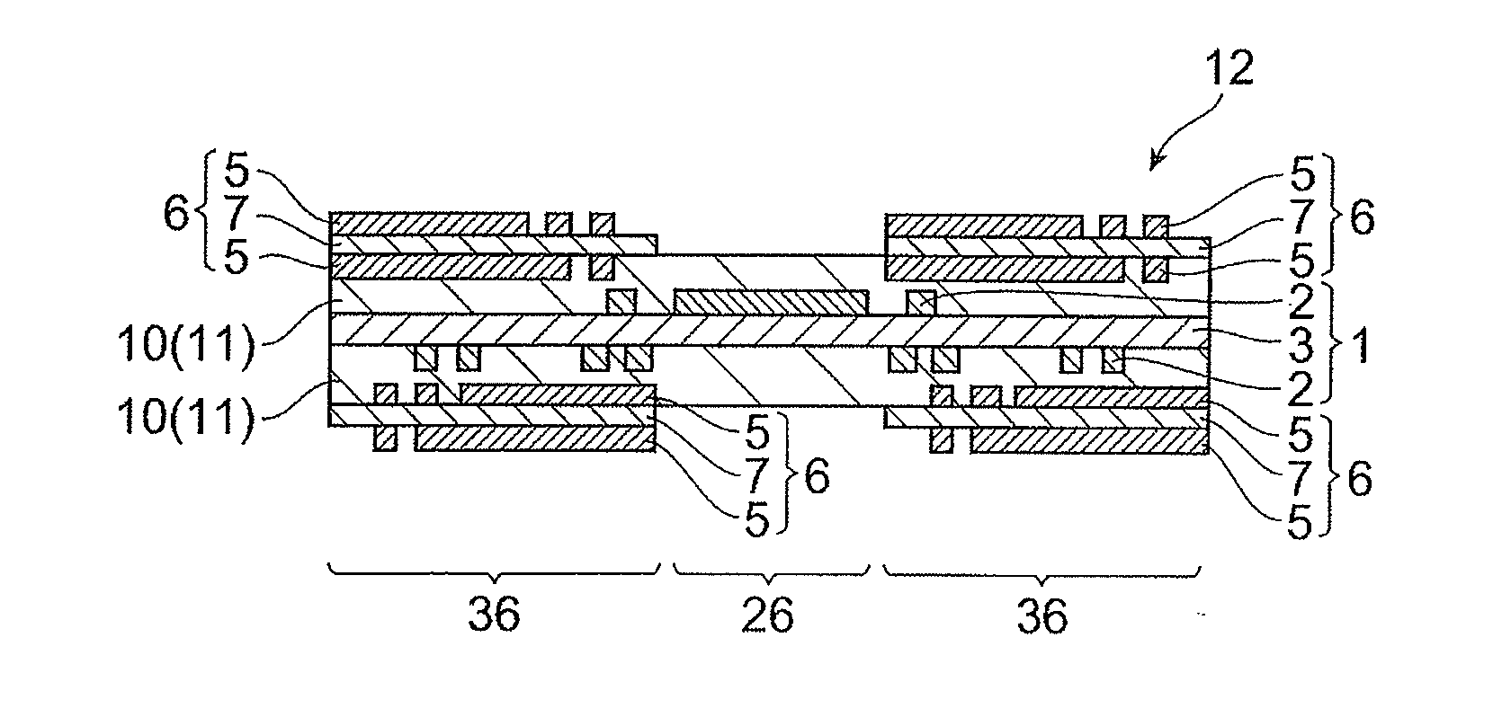
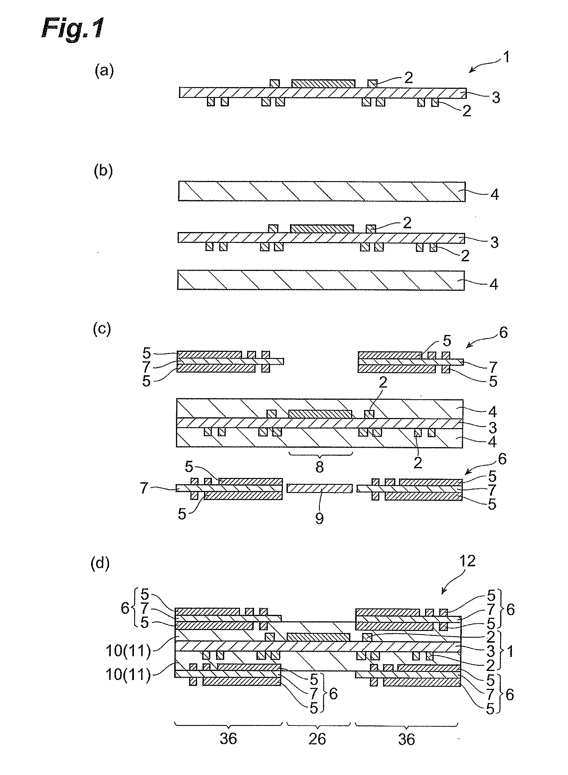
Image

Examples
example 1
[0080]First, a 50 μm-thick imide-based prepreg (product of Hitachi Chemical Co., Ltd.) including a 0.019 mm-thick glass cloth (1027, product of Asahi Shwebel) was prepared. Next, 18 μm-thick copper foils (F2-WS-18, product of Furukawa Circuit Foil Co., Ltd.) were superposed on both sides of the prepreg with the bonding surfaces facing the prepreg. This was then pressed with pressing conditions of 230° C., 90 minutes, 4.0 MPa to form a double-sided copper clad laminate.
[0081]Both sides of the double-sided copper-clad laminate were laminated with MIT-225 (product of Nichigo-Morton Co., Ltd., 25 μm thickness) as an etching resist and worked into prescribed patterns by a conventional photolithography technique. The copper foil was then etched with a ferric chloride-based copper etching solution to form patterns. It was then rinsed and dried to produce a foldable printed circuit board (first printed circuit board) comprising a first conductor circuit.
[0082]Both sides of the printed circu...
example 2
[0085]First, a 50 μm-thick acrylic / epoxy-based prepreg (product of Hitachi Chemical Co., Ltd.) including a 0.019 mm-thick glass cloth (1027, product of Asahi Shwebel) was prepared. Next, 18 μm-thick copper foils (HLA-18, product of Nippon Denkai Co., Ltd.) were superposed on both sides of the prepreg with the bonding surfaces facing the prepreg. This was then pressed with pressing conditions of 230° C., 90 minutes, 4.0 MPa to form a double-sided copper clad laminate.
[0086]Both sides of the double-sided copper-clad laminate were laminated with MIT-225 (product of Nichigo-Morton Co., Ltd., 25 μm thickness) as an etching resist and worked into prescribed patterns by a conventional photolithography technique. The copper foil was then etched with a ferric chloride-based copper etching solution to form patterns. It was then rinsed and dried to produce a printed circuit board (first printed circuit board) comprising a foldable first conductor circuit.
[0087]Both sides of the printed circuit...
example 3
[0090]Both sides of a double-sided copper-clad polyimide film (product of Ube Industries, Ltd.) were laminated with MIT-215 (product of Nichigo-Morton Co., Ltd., 15 μm thickness) as an etching resist and worked into prescribed patterns by a conventional photolithography technique. The copper foil was then etched with a ferric chloride-based copper etching solution to form patterns. It was then rinsed and dried to produce a printed circuit board (first printed circuit board) comprising a foldable first conductor circuit.
[0091]Both sides of the printed circuit board were vacuum laminated with 35 μm-thick imide-based adhesive films (product of Hitachi Chemical Co., Ltd.) at 100° C.
[0092]Separately, prescribed circuit patterns were formed on both sides of MCL-I-67-0.2t-18 copper-clad laminates (product of Hitachi Chemical Co., Ltd.) by an ordinary photolithography technique, and rigid wiring boards (second printed circuit boards) comprising second conductor circuits were prepared.
[0093]...
PUM
| Property | Measurement | Unit |
|---|---|---|
| Thickness | aaaaa | aaaaa |
| Density | aaaaa | aaaaa |
| Flexibility | aaaaa | aaaaa |
Abstract
Description
Claims
Application Information