
Method for forming a sacrificial sandwich structure

a sandwich structure and sacrificial material technology, applied in the direction of basic electric elements, electrical equipment, semiconductor devices, etc., can solve the problems of photoresist (resist) experiencing peeling, difficult dry etching process, exposed metal film cannot be completely etched away,

Inactive Publication Date: 2010-03-18
TAIWAN SEMICON MFG CO LTD
View PDF8 Cites 18 Cited by
  • Summary
  • Abstract
  • Description
  • Claims
  • Application Information

AI Technical Summary

Benefits of technology

[0002]In advanced technology nodes of semiconductor industry, metal and high k dielectric material are used to form a metal gate stack of a field-effect transistor (FET). When forming the metal gate stack, one or more metal layers are patterned including deposition and etching. During the metal etch, the etch processing window is not enough and the photoresist (resist) may experience a peeling issue at the metal etch step. Particularly, the usual dry etch process is challenging since the material to be etched is very thin and weak. The exposed metal film cannot be completely etched away and the patterned resist cannot be removed by solvent strip after the dry etch. The substrate also shows damage after the dry etch process. For an usual wet etch process, the wet etch solution can penetrate into the interface between the patterned resist and the metal film and oxidize the metal film underlying the patterned resist, therefore further changing the metal film and degrading the device performance. Moreover, the patterned resist may peel away from the underlying metal film during the wet etch process.

Problems solved by technology

During the metal etch, the etch processing window is not enough and the photoresist (resist) may experience a peeling issue at the metal etch step.
Particularly, the usual dry etch process is challenging since the material to be etched is very thin and weak.
The exposed metal film cannot be completely etched away and the patterned resist cannot be removed by solvent strip after the dry etch.
The substrate also shows damage after the dry etch process.
For an usual wet etch process, the wet etch solution can penetrate into the interface between the patterned resist and the metal film and oxidize the metal film underlying the patterned resist, therefore further changing the metal film and degrading the device performance.
Moreover, the patterned resist may peel away from the underlying metal film during the wet etch process.

Method used


Image

  • Method for forming a sacrificial sandwich structure
  • Method for forming a sacrificial sandwich structure
  • Method for forming a sacrificial sandwich structure

Examples


Embodiment Construction

[0006]It is to be understood that the following disclosure provides many different embodiments, or examples, for implementing different features of various embodiments. Specific examples of components and arrangements are described below to simplify the present disclosure. These are, of course, merely examples and are not intended to be limiting. In addition, the present disclosure may repeat reference numerals and / or letters in the various examples. This repetition is for the purpose of simplicity and clarity and does not in itself dictate a relationship between the various embodiments and / or configurations discussed. Moreover, the formation of a first feature over or on a second feature in the description that follows may include embodiments in which the first and second features are formed in direct contact, and may also include embodiments in which additional features may be formed interposing the first and second features, such that the first and second features may not be in d...


PUM

PropertyMeasurementUnit
thicknessaaaaaaaaaa
thicknessaaaaaaaaaa
thicknessaaaaaaaaaa

Abstract

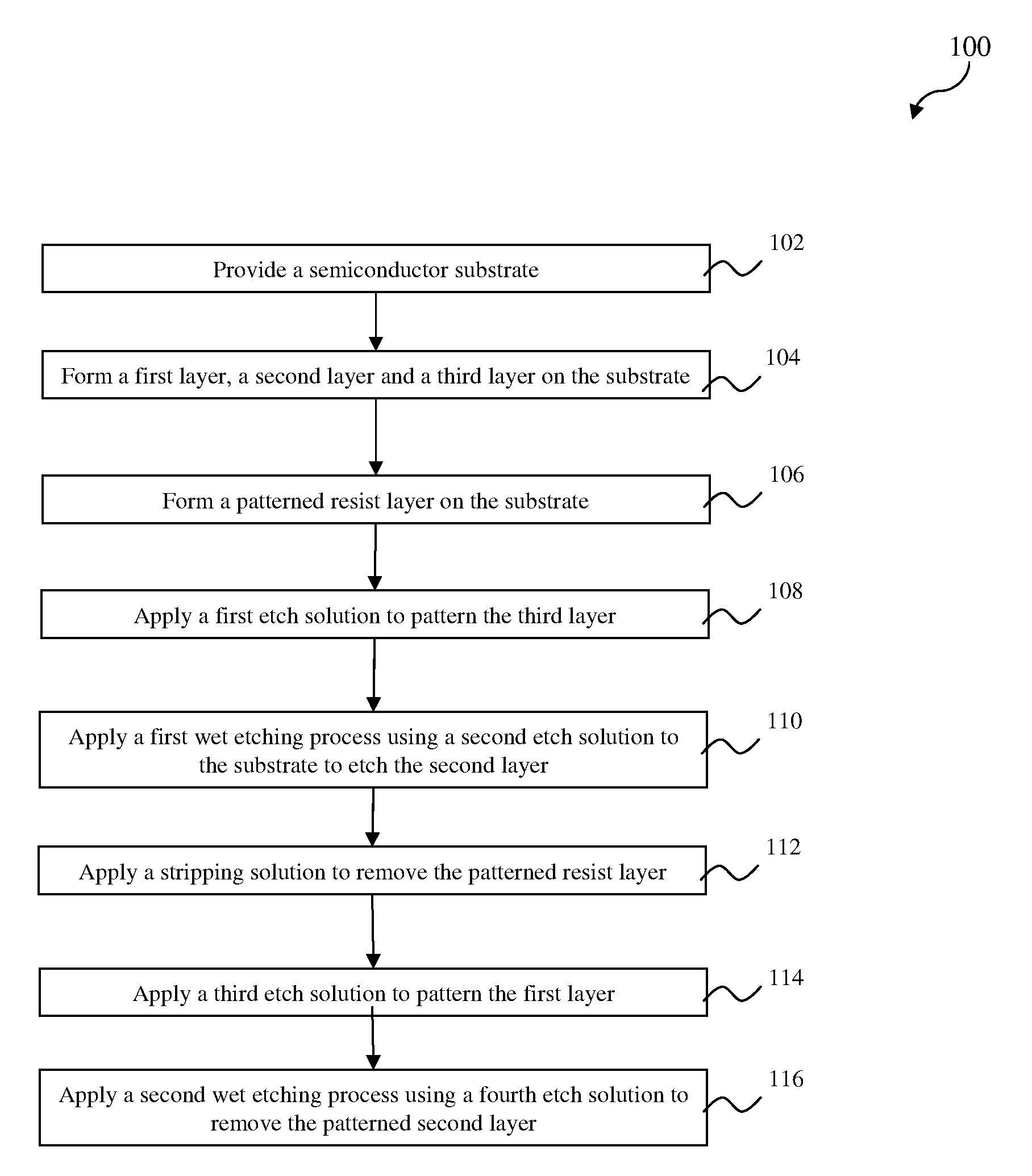
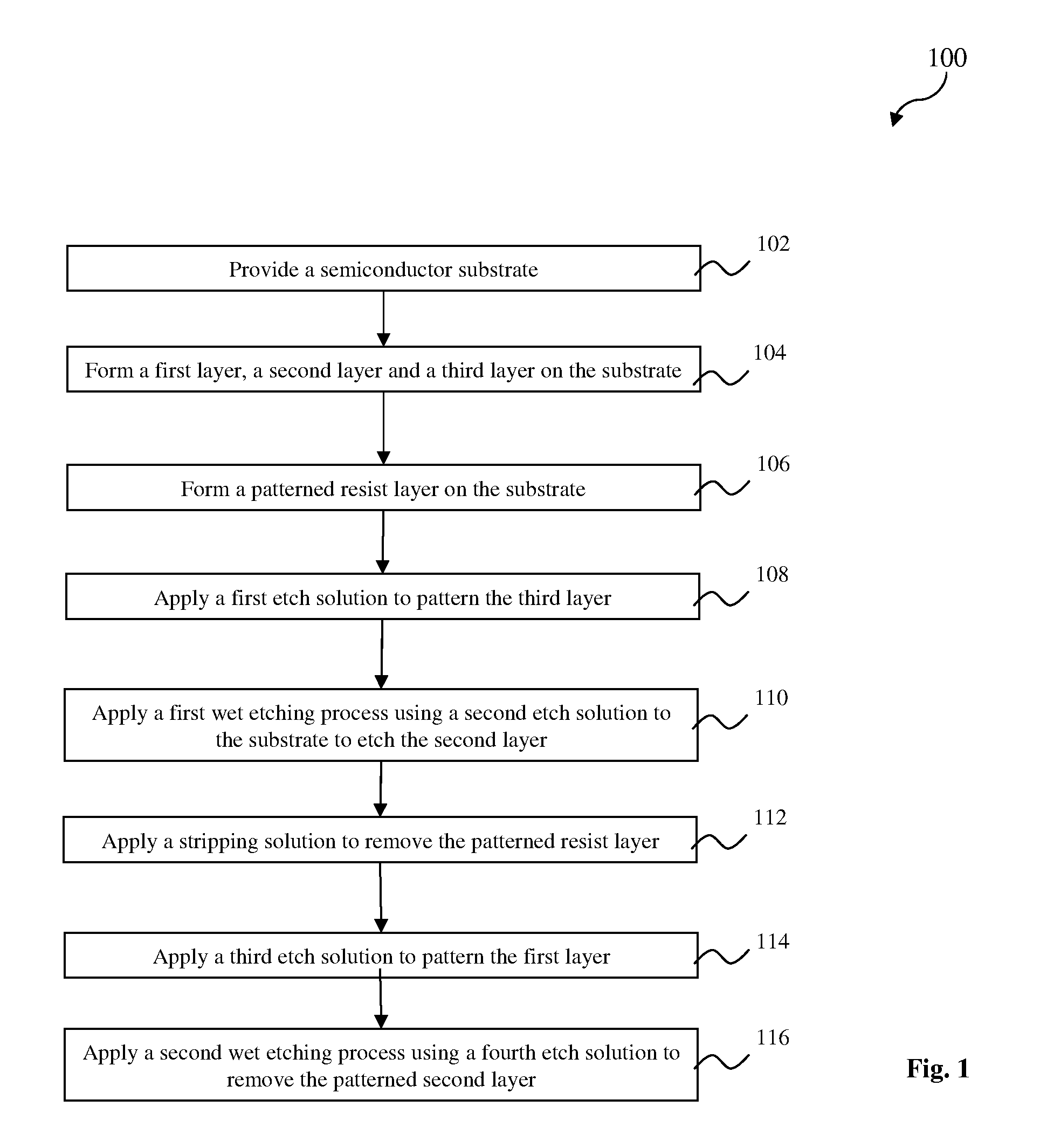
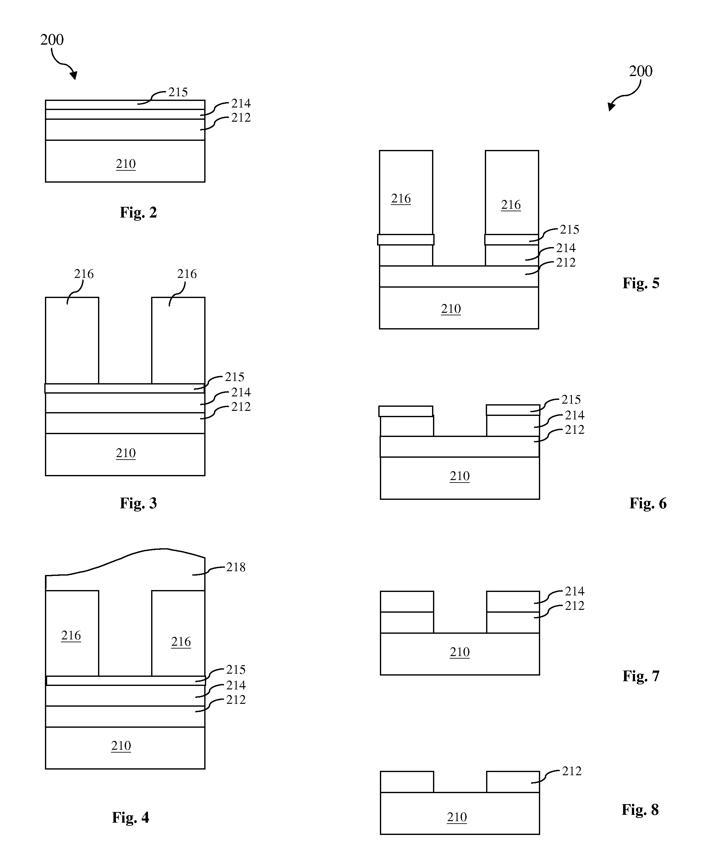
The present disclosure provides a method for making a semiconductor device. The method includes forming a first material layer on a substrate; forming a second material layer on the first material layer; forming a sacrificial layer on the second material layer; forming a patterned resist layer on the sacrificial layer; applying a first wet etching process using a first etch solution to the substrate to pattern the sacrificial layer using the patterned resist layer as a mask, resulting in a patterned sacrificial layer; applying an ammonia hydroxide-hydrogen peroxide-water mixture (APM) solution to the substrate to pattern the second material layer, resulting in a patterned second material layer; applying a second wet etching process using a second etch solution to the substrate to pattern the first material layer; and applying a third wet etching process using a third etch solution to remove the patterned sacrificial layer.

Description

PRIORITY DATA[0001]This application claims priority to Provisional Application Ser. No. 61 / 097,014 filed on Sep. 15, 2008, entitled “Method for Forming a Sacrificial Sandwich Structure,” the entire disclosure of which is incorporated herein by reference.BACKGROUND[0002]In advanced technology nodes of semiconductor industry, metal and high k dielectric material are used to form a metal gate stack of a field-effect transistor (FET). When forming the metal gate stack, one or more metal layers are patterned including deposition and etching. During the metal etch, the etch processing window is not enough and the photoresist (resist) may experience a peeling issue at the metal etch step. Particularly, the usual dry etch process is challenging since the material to be etched is very thin and weak. The exposed metal film cannot be completely etched away and the patterned resist cannot be removed by solvent strip after the dry etch. The substrate also shows damage after the dry etch process....

Claims


Application Information

Patent Timeline
Patent Type & Authority Applications(United States)
IPC IPC(8): H01L21/28H01L21/306
CPCH01L21/0271H01L21/28079H01L21/28088H01L21/28123H01L29/517H01L21/31133H01L21/32132H01L21/32139H01L21/31111
Inventor CHANG, CHING-YU
Owner TAIWAN SEMICON MFG CO LTD
Learn More