Prosthesis shaft with active air release

Inactive Publication Date: 2010-03-18
OTTO BOCK HEALTHCARE IP GMBH & CO KG
View PDF1 Cites 74 Cited by
  • Summary
  • Abstract
  • Description
  • Claims
  • Application Information

AI Technical Summary

Benefits of technology

[0012]Following what has been said above, the object of the invention is to create a simple system for reducing the pressure in the interior of a socket between the skin of the stump and the inner wall of the socket, which system is not susceptible to mechanical failure, does not add any appreciable additional wei

Problems solved by technology

The systems according to the prior art have the disadvantage of, on the one hand, being susceptible to mechanical failure and, on the other hand, of entailing a not inconsiderable additional weight, which has to be carried around by the prosthesis wearer and has to be accelerated and decelerated on each step, which requires considerable additional energy.
All of this is very cumbersome and also limits the mobility of the prosthesis wearer.
Moreover, the necessary maintenance work and, if appropriate, the replacement of consumables such as batteries, entails additional cos

Method used


Image

  • Prosthesis shaft with active air release
  • Prosthesis shaft with active air release
  • Prosthesis shaft with active air release

Examples


Example

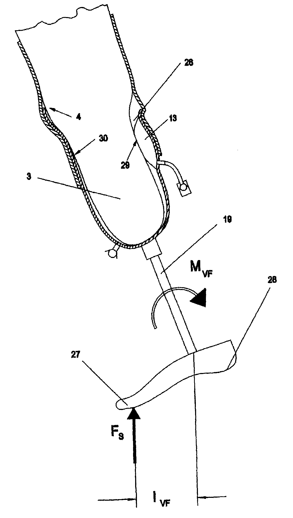
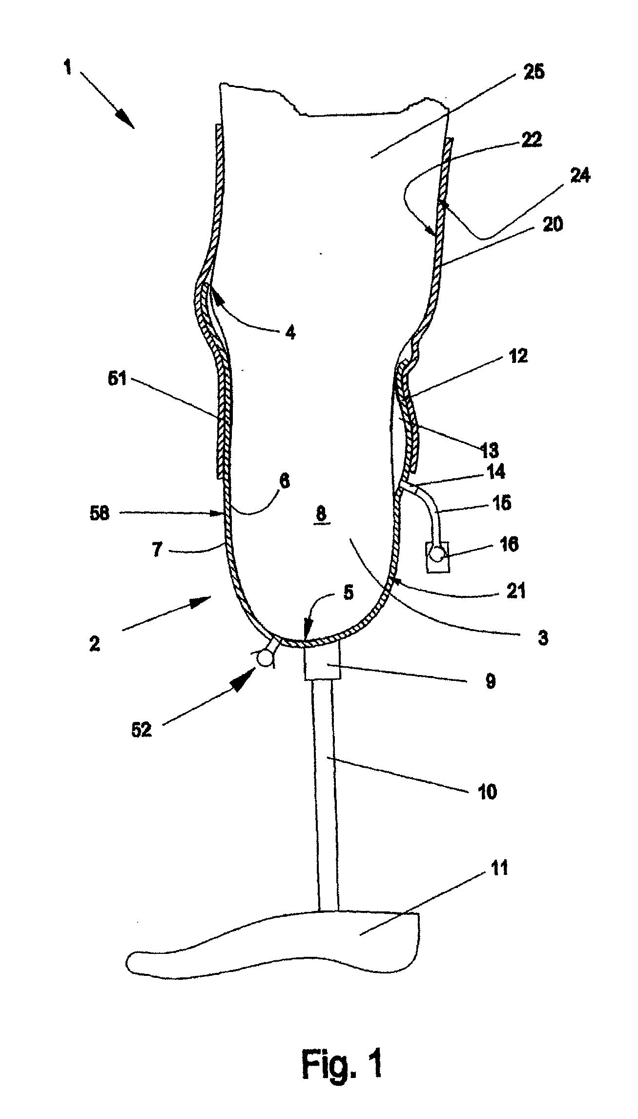
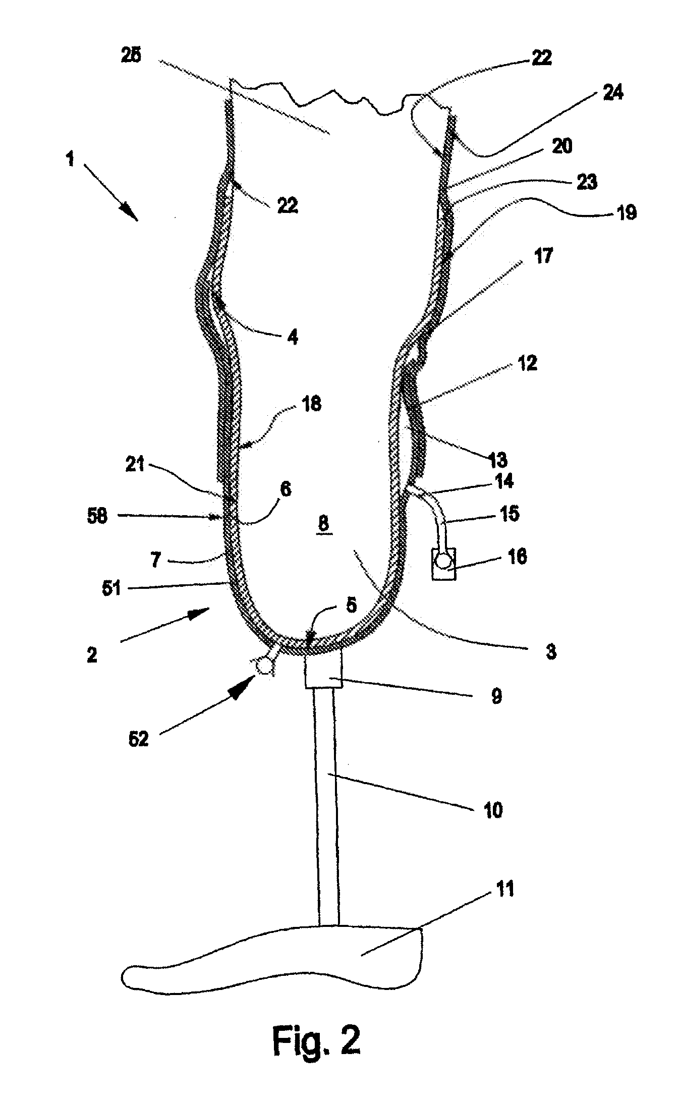
[0034]FIG. 1 illustrates the invention, using the example of a below-knee prosthesis (1) which is shown cut away in the sagittal plane. The socket (2), which receives the stump (3) and is adapted to it, is substantially cup-shaped with an open end (4) at the top, and with a closed, lower end (5) directed toward the ground. The socket (2) has an inwardly directed inner face (6) and an outwardly directed outer face (7). The inner face (6) forms a cup-shaped space (8) that receives the stump (1). The socket (2) is connected to an artificial foot (11) via an adapter piece (9) which is secured on the socket (2) and which has a tubular extension part (10). In the illustrative embodiment of the invention shown here, the rear (dorsal) socket wall has, in the upper (proximal) area, an elongate oval bulge (12) which forms a space for receiving a pump chamber (13). Although the bulge (12) is not absolutely necessary in all cases, it is advantageous for avoiding pressure sores. It is only as de...


PUM


Abstract

The invention relates to a cup-shaped prosthesis shaft consisting of an air-tight and essentially rigid material comprising a sealing means for protecting against the entry of air from the proximal open side, said shaft being used in prostheses for replacing limbs. The inside of the shaft is provided with at least one pump device such that relative movements between the stump and the shaft during the use of the prosthesis pump air out of the inside of the prosthesis shaft via flow channels and monoway valves to the outside of the prosthesis shaft. The pump action is obtained by varying the volume of a compartment formed from flexible or elastic films, said compartment being arranged adjacently to the strump in the main extension thereof. The compartment is either fixed to the inner wall of a rigid prosthesis shaft, or built into the wall of a flexible and elastic removable stump coating which is arranged, as part of the prosthesis shaft, between the stump and a rigid frame.

Description

[0001]The invention relates to a prosthesis socket for use in an artificial replacement for an amputated limb, according to the preamble of claim 1.GENERAL INTRODUCTION [0002]In prosthesis manufacture, a cup-shaped container made from substantially flexurally stiff material is generally molded to match the stump and, in accordance with the rules of prosthetics, is shaped in such a way as to permit painless transfer of forces via the amputation stump through this so-called prosthesis socket. In the case of a prosthesis to compensate for loss of part of the upper limb, the forces that are to be transferred via the socket are generally pressure forces and tensile forces and moments that arise on the hand during use of an arm, for example. If the prosthesis compensates for loss of part of the lower limb, the forces arise primarily from the static and dynamic transfer of the body weight during locomotion. In addition to these pressure forces and bending and rotation moments, however, leg...

Claims


Application Information

Patent Timeline
IPC IPC(8): A61F2/80
CPCA61F2/60A61F2/7843A61F2002/805A61F2002/742A61F2002/748A61F2/80A61F2/742A61F2/748
Inventor CARSTENS, FELIX
Owner OTTO BOCK HEALTHCARE IP GMBH & CO KG
Why Eureka
Try Eureka