Adaptive compression of computed tomography projection data

a computed tomography and projection data technology, applied in the field of compression and decompression of projection data, can solve the problems of reducing the efficiency of data transfer, reducing the bandwidth of data delivered, and requiring large volumes of projection data to be transferred and stored. the effect of reducing the storage capacity

Inactive Publication Date: 2010-03-18
MOOG INC
View PDF46 Cites 28 Cited by
  • Summary
  • Abstract
  • Description
  • Claims
  • Application Information

AI Technical Summary

Benefits of technology

[0013]Embodiments of the present invention have been made in consideration of the foregoing conventional problems. An object of the present invention is to compress CT projection data. The benefits of compressing CT projection data include increasing the efficiency of data transfer across the slip ring interface of a CT scanner, reducing the bandwidth of data delivered to a storage subsystem such as a RAID array and reducing the storage capacity required for a set of projection data in a CT imaging system. A further object of the present invention is to provide a fixed output bit rate. User-specified control of the output bit rate, or bits per sample, of the compressed data results in predictable data transfer rates and data storage requirements. Additional cost savings for CT system components can be achieved when the user-specified compression ratio is an integer value, such as 2:1. For example, a fixed 2:1 compression ratio allows some components of the system such as memory, field programmable gate arrays (FPGA), cables for data transfer and disk drives for data storage to be reduced by half.

Problems solved by technology

However, like medical CT systems, large volumes of projection data require data transfer and storage.
The large volumes of projection data acquired by a data acquisition subsystem of a CT system create a burden on system resources for data transfer and data storage.
Limitations in data transfer bandwidth delays the availability of projection data for the reconstruction and display of an image of the object being scanned.
Applying a compression algorithm to the projection data in the Radon transform domain will not produce the same results as applying the same algorithm to the reconstructed image in the spatial domain because of the mathematical relationship between the projection data and the reconstructed image.
The bit rate of the compressed data can vary unpredictably in the above techniques because the regions of interest defined and lossless compression are data dependent.
A FIFO interface is more complicated than a fixed-rate interface, since it requires additional control signals (half full, almost full, almost empty, etc.).
Another disadvantage of the above approaches is computational complexity, depending on which compression method is applied.
If lossless compression does not give adequate reductions in the bit rate of the compressed samples, then lossy compression may be necessary to provide sufficient reduction of the bit rate.
Lossy compression creates a tradeoff between the bit rate of the compressed samples and the distortion in the decompressed samples.

Method used


Image

  • Adaptive compression of computed tomography projection data
  • Adaptive compression of computed tomography projection data
  • Adaptive compression of computed tomography projection data

Examples


Embodiment Construction

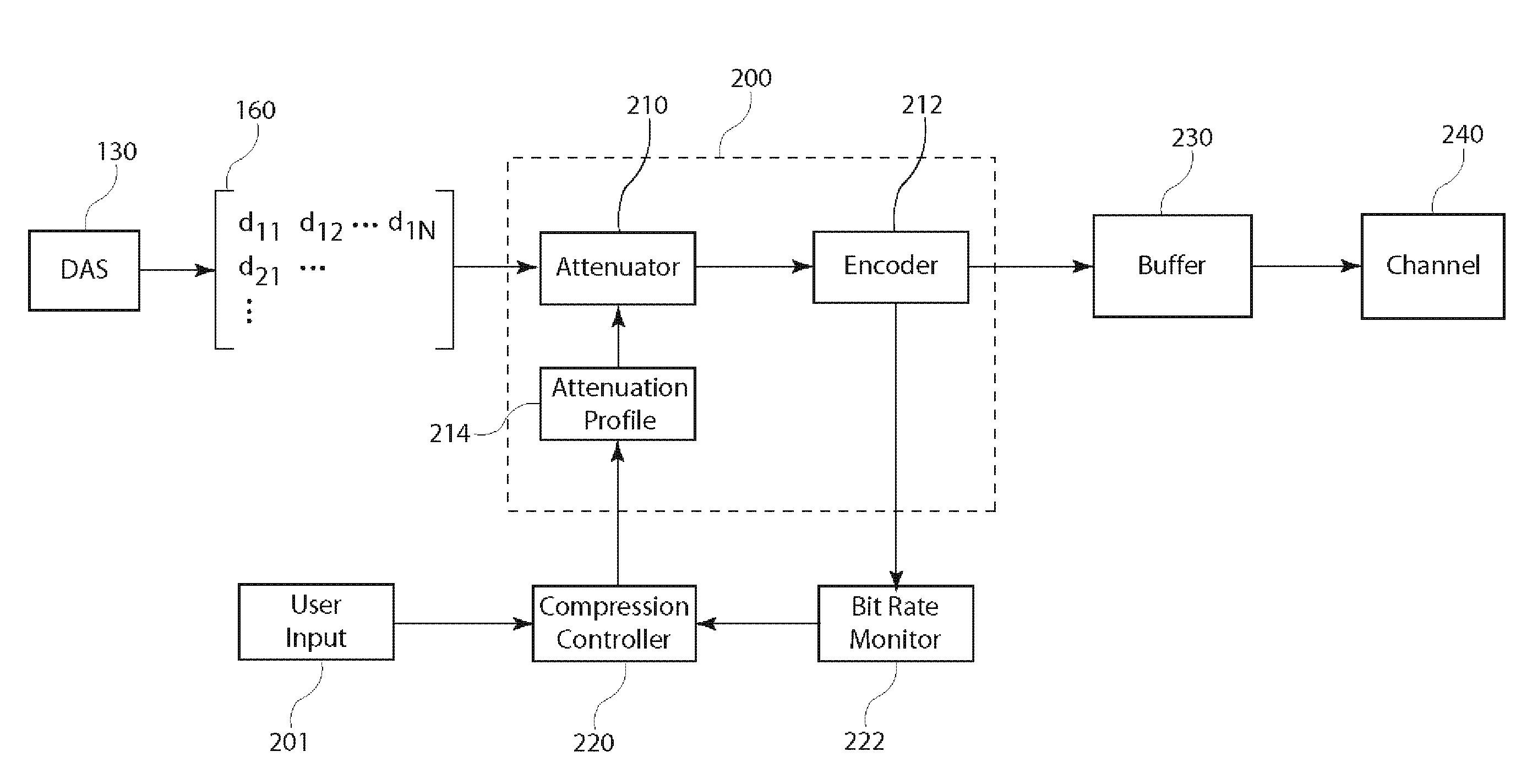
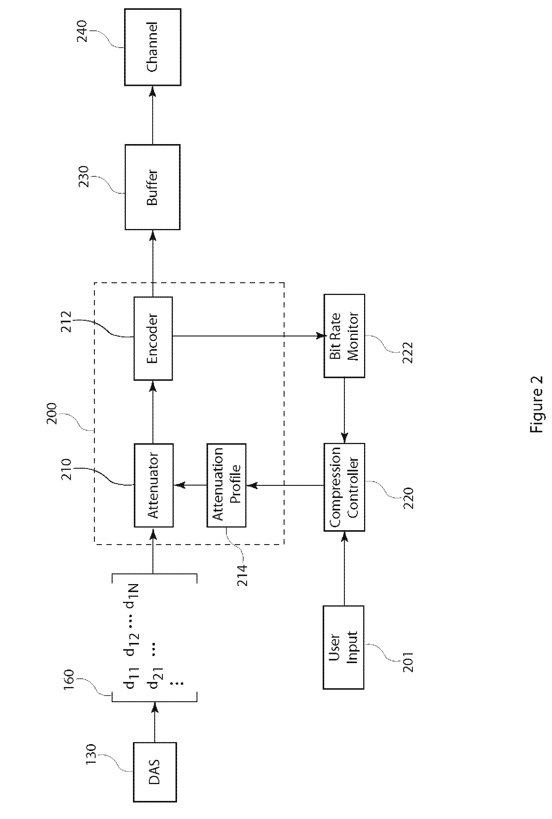
[0033]The present invention is directed to compression and decompression of projection data in the Radon transform domain, also known as the projection domain or sinogram domain. Compression of projection data allows more efficient data transfer from the data acquisition subsystem of a CT system to a storage subsystem and an image reconstruction processor. Later decompression of the compressed projection data is applied prior to image reconstruction of a spatial domain image. Compression and decompression can be applied to one set of projection data resulting from one view or to multiple sets of projection data resulting from multiple views. The present invention is independent of the number of views used by the image reconstruction processor to compute a spatial domain image.

[0034]Embodiments of the present invention can be used for compressing and decompressing projection data in a medical computerized tomography scanner for generating cross-sectional images of a human body and in...


PUM


Abstract

A compression subsystem for a computed tomography system compresses projection data to for efficient data transfer and storage. The compression includes applying an attenuation profile to an array of projection data samples. The attenuation profile is a function of sample coordinates and determines attenuation values applied to the samples. The attenuated samples are encoded and packed for data transfer. Alternatively, difference operators are applied to the attenuated samples and the differences are encoded. The average number of bits per compressed sample is monitored and the attenuation profiles can be modified to achieve a desired number of bits per compressed sample. The compressed samples are decompressed prior to image reconstruction processing. Decompression includes decoding the compressed samples and applying a gain profile to the decoded samples to restore the original dynamic range. This abstract does not limit the scope of the invention as described in the claims.

Description

BACKGROUND OF THE INVENTION[0001]The present invention relates to compression and decompression of projection data acquired for computed tomography (CT), particularly to adapting attenuation of the projection data samples to achieve a desired number of bits per sample in the compressed data.[0002]In a CT imaging system, multiple x-ray radiographic views of an object produce sets of projection data. Each line of projection data represents an integration of density values of internal structures within a plane, or slice, of the object. From the multiple sets of projection data, the CT imaging system produces two-dimensional (2D) cross-sectional images and three-dimensional (3D) images of the internal structures of the object. The images are obtained through application well-known image reconstruction algorithms to the sets of projection data. The techniques that reconstruct cross-sectional images or three-dimensional images from multiple sets of projection data are broadly referred to ...

Claims


Application Information

Patent Timeline
Patent Type & Authority Applications(United States)
IPC IPC(8): G06F17/30G06F11/00
CPCG06T9/00A61B6/032A61B6/56A61B6/4233A61B6/4078A61B6/03
Inventor WEGENER, ALBERT W.LING, YI
Owner MOOG INC
Why Eureka
Try Eureka