Sub-surface imaging using antenna array for determing optimal oil drilling site

a technology of optimal oil drilling and subsurface imaging, which is applied in the direction of instruments, borehole/well accessories, surveillance, etc., can solve the problems of reducing the flow of oil to the well, contributing to additional production costs, and existing techniques still cannot adequately enable the complete recovery of all of the oil within the reservoir

Inactive Publication Date: 2010-03-25
LOCKHEED MARTIN CORP
View PDF23 Cites 7 Cited by
  • Summary
  • Abstract
  • Description
  • Claims
  • Application Information

AI Technical Summary

Benefits of technology

[0007]An array of electromagnetic (EM) receiver antennae is arranged and operated in conjunction with the operation of an array of EM transmitter antennae for mapping subsurface features of a reservoir. Mapping is performed according to the relative intensities, frequencies, phase shifts, and / or other reflected signal parameters of the reflections received by the receiver antennae (relative to the transmit signals) associated with a given location or target area within a reservoir. Such mapping aids in determining an optimal location of a production well or the location of an auxiliary well relative to the production well.

Problems solved by technology

Eventually, the flow of oil to the well will decrease to a point where the amount of oil available from the well no longer justifies the costs of production, which includes the costs of removing and transporting the oil.
Such mechanisms tend to forcibly displace the oil in order to move the oil in the direction of the production well.
Such methods, however, often require drilling additional bore holes into the reservoir, heating the secondary materials and flooding the materials into the reservoir, in addition to post processing requirements for removing and filtering the secondary materials from the recovered oil.
All of these contribute to additional production costs.
Moreover, existing techniques still do not adequately enable complete recovery of all of the oil within the reservoir.
Thus, in many cases, oil recovery may be discontinued despite a substantial amount of oil remaining within the reservoir, because extraction of the remaining oil is too expensive or too difficult given the current recovery methods.

Method used


Image

  • Sub-surface imaging using antenna array for determing optimal oil drilling site
  • Sub-surface imaging using antenna array for determing optimal oil drilling site
  • Sub-surface imaging using antenna array for determing optimal oil drilling site

Examples


Embodiment Construction

[0026]The following description of the preferred embodiments is merely by way of example and is in no way intended to limit the invention, its applications, or uses.

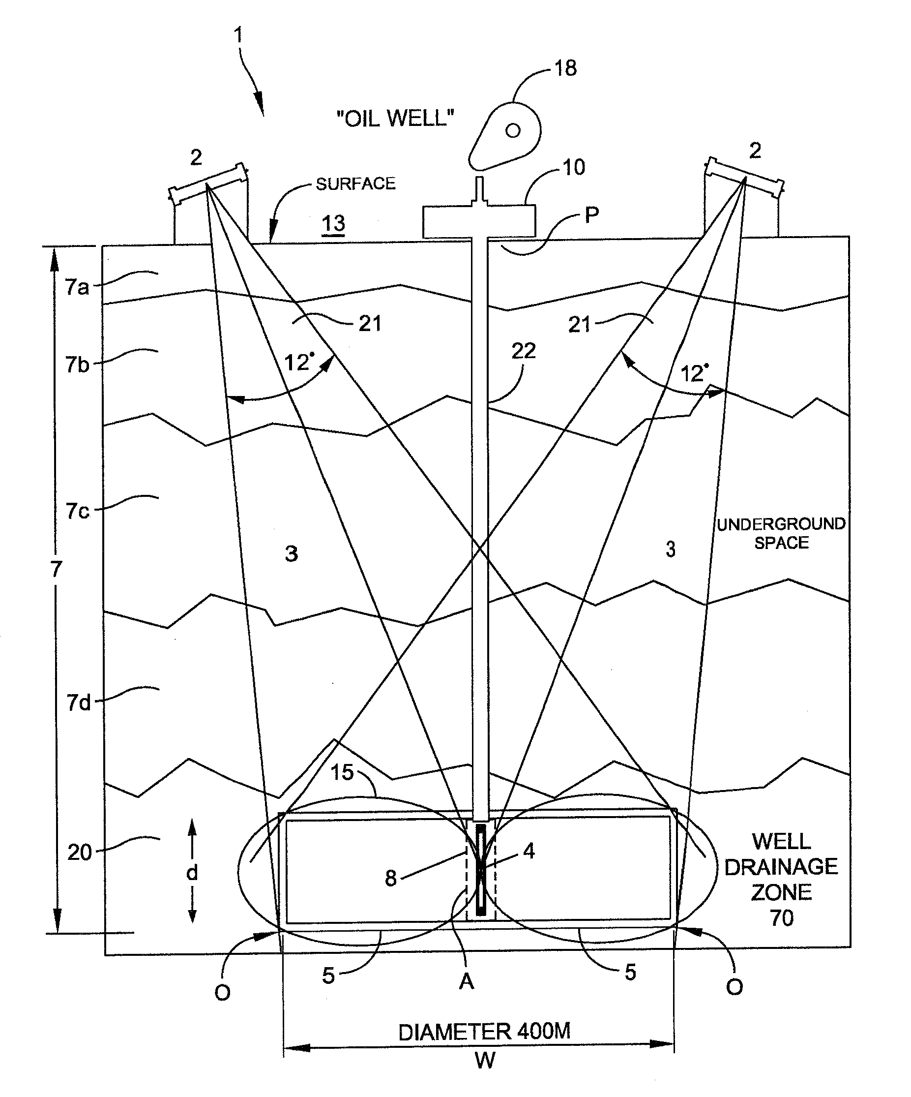
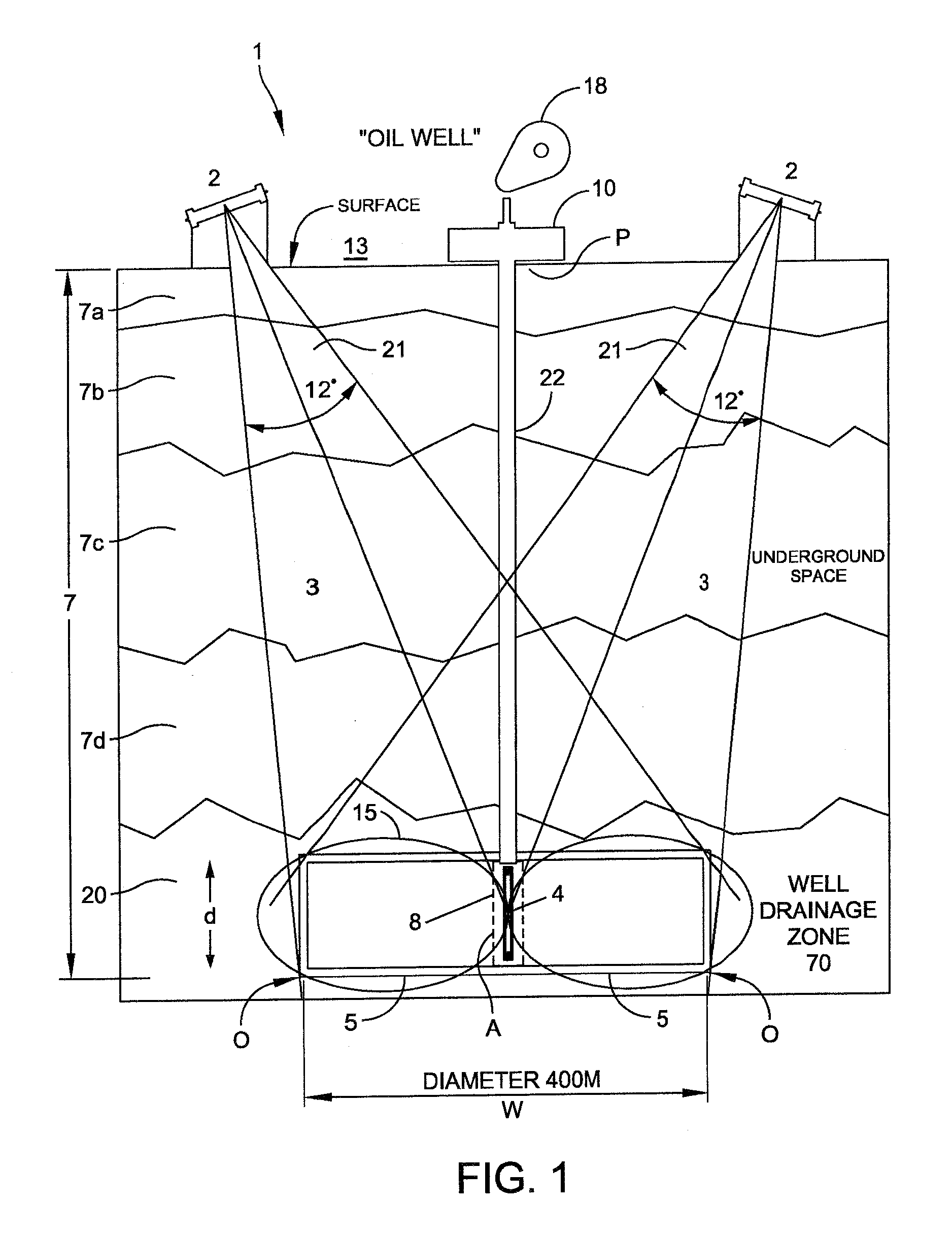
[0027]Referring to FIG. 1, there is shown a schematic illustration of a system 1 for imparting EM signals into a permeable reservoir formation containing crude oil to enhance crude oil flow and recovery according to an embodiment of the present invention. As shown in FIG. 1, a production well 10 positioned on the terrain surface is drilled through geological strata indicated generally as 7 to form a borehole 22. As shown, the geological strata 7 may contain multiple layers (e.g. 7a, 7b, 7c, 7d) of material, such as soil, rock, shale, sand, water, underground space, and the like. Borehole 22 extends through the strata to a formation layer 20 defining a well drainage zone or reservoir 70 containing crude oil deposits (e.g. crude oil particles) for extraction. A filter casing 8 such as a perforated or mesh structure support...


PUM


Abstract

The invention provides for systems and methods of enhancing crude oil recovery providing an array of electromagnetic receiver antennae arranged and operated in conjunction with an array of far field electromagnetic transmitter antennae for mapping subsurface features of a reservoir. Mapping is performed according to the relative intensities, frequencies, phase shifts, and/or other reflected signal parameters of the reflections received by the receiver antennae (relative to the transmit signals) associated with a given location or target area within a reservoir. Such mapping aids in determining an optimal location of a production well or the location of an auxiliary well relative to the production well.

Description

CROSS-REFERENCE TO RELATED APPLICATIONS[0001]This application claims priority to Provisional Patent Application Ser. No. 61 / 090,529 entitled “Electromagnetic Based System and Method For Enhancing Subsurface Recovery of Fluid Within a Permeable Formation” filed Aug. 20, 2008, Provisional Patent Application Ser. No. 61 / 090,533 entitled “System and Method to Measure and Track Movement of a Fluid in an Oil Well and / or Water Reservoir Using RF Transmission” filed Aug. 20, 2008, Provisional Patent Application No. Ser. No. 61 / 090,536 entitled “Sub Surface RF Imaging Using An Antenna Array for Determining Optimal Oil Drilling Site” filed Aug. 20, 2008 and Provisional Patent Application Ser. No. 61 / 090,542 entitled “RF System and Method for Determining Sub-Surface Geological Features at an Existing Oil Web Site” filed Aug. 20, 2008, the subject matter thereof incorporated by reference in its entirety.FIELD OF THE INVENTION[0002]This invention relates generally to subsurface fluid recovery sy...

Claims


Application Information

Patent Timeline
Patent Type & Authority Applications(United States)
IPC IPC(8): E21B47/00G01V3/12G06F19/00G06K9/00
CPCE21B47/102E21B43/16Y10T137/0391E21B47/113
Inventor BENISCHEK, VINCENTCURRIE, MICHAELBASANTKUMAR, RAJNEETALYASKO, GENNADY
Owner LOCKHEED MARTIN CORP
Why Eureka
Try Eureka