Power generation system using helical turbine

a technology of power generation system and helical turbine, which is applied in the direction of mechanical energy handling, non-positive displacement fluid engine components, liquid fuel engine components, etc., can solve the problems of long construction period, water pollution, environmental pollution, etc., and achieve the effect of reducing equipment costs, preventing environmental pollution, and reducing construction costs

Active Publication Date: 2010-03-25
KOREA OCEAN RES & DEV INST
View PDF22 Cites 16 Cited by
  • Summary
  • Abstract
  • Description
  • Claims
  • Application Information

AI Technical Summary

Benefits of technology

[0009]A helical turbine power generation system according to the present invention includes a helical turbine for generating rotation force, and thus does not require a tidal power dam used for a conventional structure. Accordingly, it is possible to reduce construction costs, and at the same time to prevent environmental p...

Problems solved by technology

However, the conventional tidal power generation uses potential energy, and thus, requires a water level above a certain height.
Therefore, it is necessary to build a seawall causing ...

Method used


Image

  • Power generation system using helical turbine
  • Power generation system using helical turbine
  • Power generation system using helical turbine

Examples


first embodiment

[0021]Hereinafter, a power generation system using a helical turbine according to the present invention will be described with reference to the accompanying drawings.

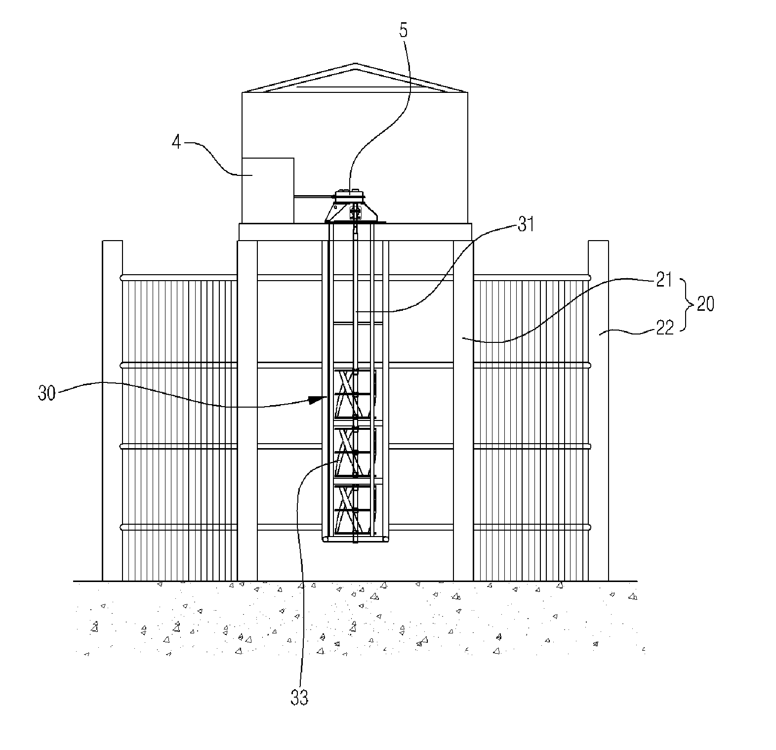
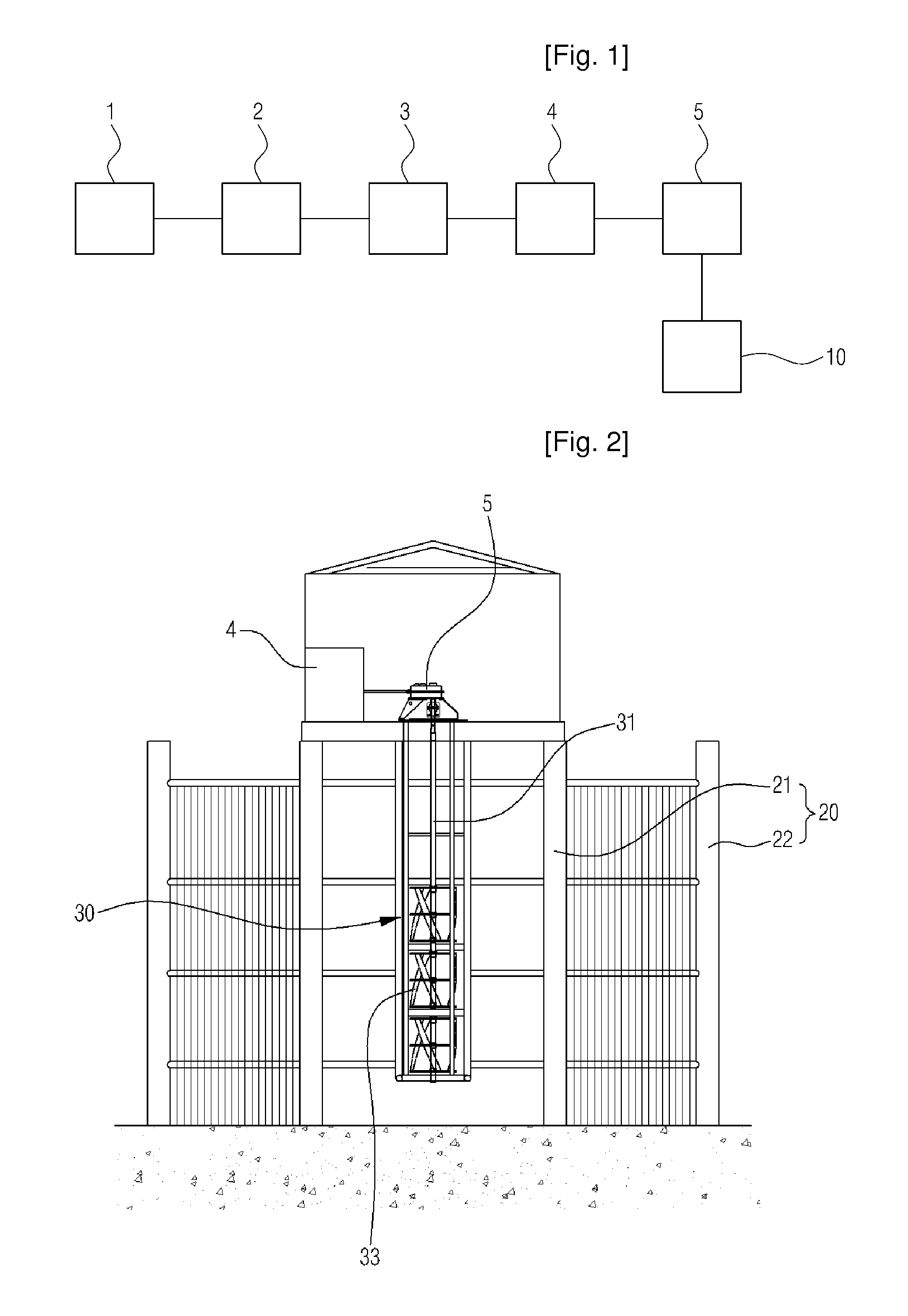
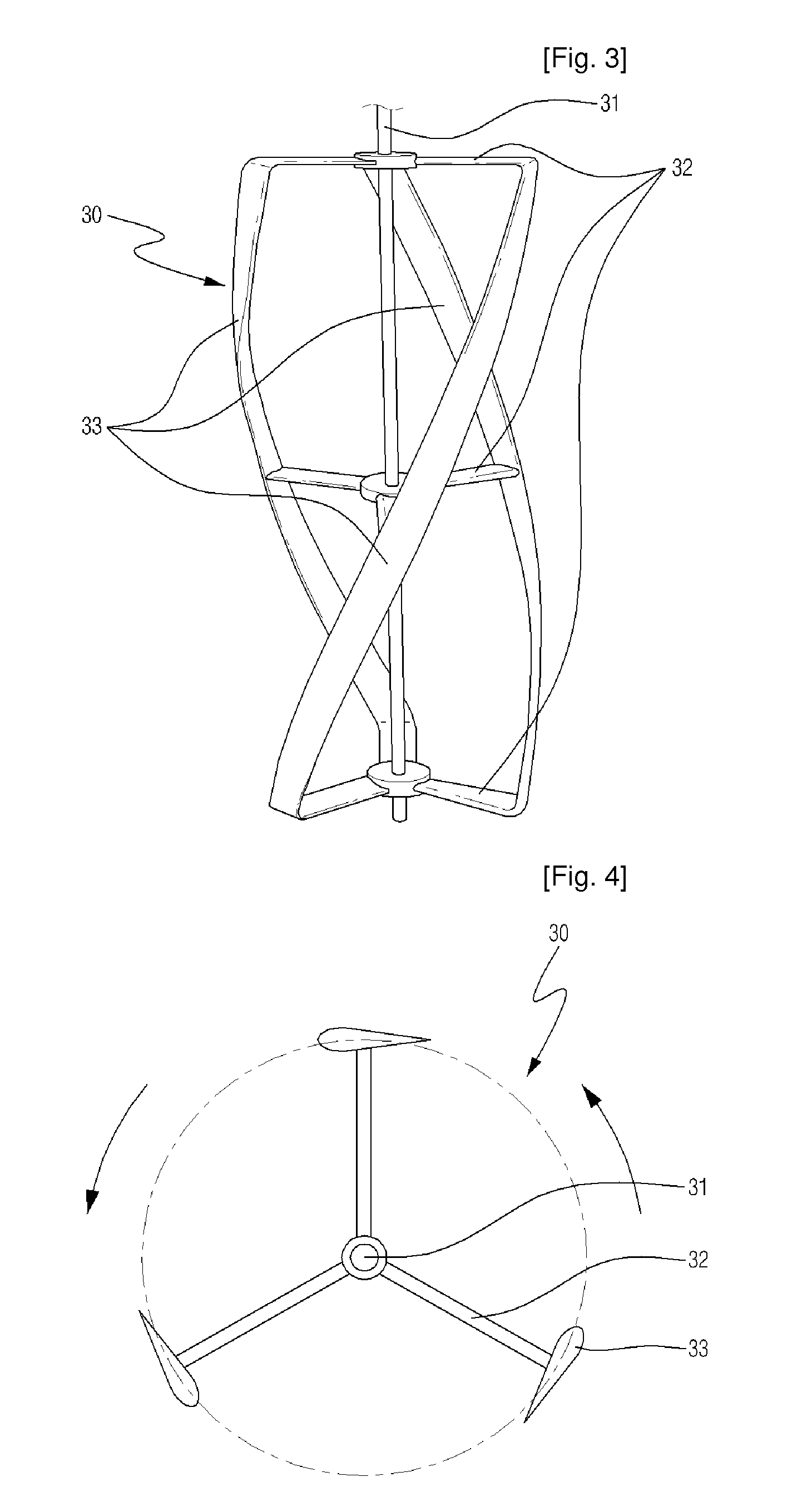
[0022]FIG. 1 is a schematic block diagram illustrating a helical turbine power generation system according to a first embodiment of the present invention; FIG. 2 is a cross-sectional view of a construction for installing the helical turbine shown in FIG. 1; FIG. 3 is a perspective view illustrating the helical turbine shown in FIG. 2; FIG. 4 is a cross-sectional view illustrating the helical turbine shown in FIG. 3; FIG. 5 is a plane view illustrating the frame shown in FIG. 2; FIG. 6 is a partially enlarged cross-sectional view illustrating “A” shown in FIG. 5.

[0023]As shown in the drawings, a helical turbine power generation system according to a first embodiment of the present invention includes: a helical turbine 30 rotatably provided in a frame 20 provided in fluid; a step-up gear 5 for increasing a rotational velo...

second embodiment

[0030]In addition to the helical turbine 30 as described above, as shown in FIGS. 7 and 8, a helical turbine power generation system according to the present invention further includes: a plurality of additional supporting members 34 radially protruding from the shaft 31, in which the additional supporting members 34 are shorter than the supporting members 32, alternate with the supporting members 32, and are multilayered in series; and at least one additional blade 35 having a helical structure, in which the blade is connected to the ends of the additional supporting members 34, has a streamlined cross section, and twists in a longitudinal direction of the shaft 31.

[0031]Accordingly, a helical turbine power generation system according to the second embodiment of the present invention, which additionally includes the supporting members 34 and the blade 35 provided in the helical turbine 30, can achieve a big rotation force according to fluid flow. Therefore, the present invention ca...


PUM


Abstract

Disclosed is a helical turbine power generation system for generating electricity by using a helical turbine and an overload prevention generator, the system including: a helical turbine rotatably provided in a frame so as to continuously generate rotation force under unidirectional or multidirectional fluid flow; a step-up gear for increasing a rotational velocity of the helical turbine up to a level required for generating electricity; and an overload prevention generator for generating electricity by using the rotational velocity transferred from the step-up gear, and for preventing overload caused by a sudden increase in a rotational velocity. Therefore, it is possible to reduce equipment costs and to prevent environmental pollution.

Description

TECHNICAL FIELD[0001]The present invention relates to a power generation system using a helical turbine, and more particularly to a helical turbine power generation system, in which kinetic energy of a helical turbine obtaining a rotation force by tidal water flow energy can be converted into electrical energy by using a wound rotor induction generator.BACKGROUND ART[0002]In general, a turbine refers to a machine or an apparatus for converting energy included in fluids (such as, water, gas, steam, etc.) into useful mechanical work. A system for generating tidal energy by using such a turbine is tidal power generation.[0003]In conventional tidal power generation, a tidal power dam is built on a back bay of a high tidal range in order to block the movement of sea water, and then the difference of water level between inside and outside of the tidal power dam, which is generated by a tidal range, is used to generate electricity. This mechanism of the tidal power generation is similar to...

Claims


Application Information

Patent Timeline
IPC IPC(8): F03B13/00
CPCF03B13/26F05B2240/40Y02E10/38F05B2270/103Y02E10/28F05B2250/25F03B13/12Y02E10/20Y02E10/30
Inventor PARK, JIN-SOONYUM, KI-DAILEE, KWANG-SOOKANG, SOK-KUHJIN, JAE-YOULLPARK, WOO-SUN
Owner KOREA OCEAN RES & DEV INST
Why Eureka
Try Eureka