Filter apparatus and method

a filter and filter body technology, applied in lighting and heating apparatus, heating types, separation processes, etc., can solve the problems of reducing the efficiency of the hvac system, proposals are subject to a number of serious problems, and the structure of the hvac filter is lacking in the prior, and achieves the effect of high-efficiency particulate air (hepa)

Inactive Publication Date: 2010-04-01
LEWIS TRAVIS
View PDF19 Cites 18 Cited by
  • Summary
  • Abstract
  • Description
  • Claims
  • Application Information

AI Technical Summary

Benefits of technology

[0011]For example, in accordance with the principles of the invention a battery powered HVAC filter system automatically removes an unclean or contaminated web of filter fabric and replaces it with a clean, fresh web of fabric on a selectively timed cycle. The frame or box for supporting the filter structure has attached to it through “pop-off” detents a supply magazine for storing an uncontaminated roll of filter fabric from which webs of fresh fabric are successively drawn in a manner that can provide up to one full year of efficient filtration. A specific feature of this invention, moreover, is the use of control chucks for maintaining sufficient tension in the fresh fabric web to keep the web properly exposed and positioned across the HVAC air intake while preventing slackness and wrinkle formation in the freshly exposed fabric web. The contaminated webs of fabric are rolled up in a contaminated fabric storage magazine that also is selectively attached to the box through a set of “pop-off” detents.
[0012]By removing the magazines, the leading edge of the filter fabric is drawn from a fresh roll of the fabric, and is attached to a take-up roll mandrel for spooling and storing contaminated fabric. A web of filter fabric also is drawn from the fresh roll of fabric and the entire assembly then is slipped transversely into the box. The magazines are then snap fitted to their respective ends of the box. The heretofore tedious and dirty job of threading the leading edge from a roll of fresh fabric through the passages that characterized prior art proposals is eliminated. The box also has a peripheral step that permits the filter apparatus to be seated within the air intake cavity behind the HVAC grate for many air conditioner ducts in a manner that establishes maximum filter fabric web surface area exposure to the incoming air stream. An additional advantage of this box is that the roll of dirty, used filter fabric is contained within the storage magazine on one side of the box while the clean roll is protected from contamination in the supply magazine on the other side of the box.
[0013]A secondary filter also is mounted within the box, this filter being a high efficiency particulate air (HEPA) filter. The secondary filter separates not only further particulate matter from the incoming air stream, but if carbon based it will provide maximum levels of air purification by absorbing and eliminating, from the incoming air stream irritating odors and hazardous gases.

Problems solved by technology

Although filters in high volume air conditioner systems (HVAC) should be replaced whenever the filter fabric becomes so obstructed with particulate matter that it significantly degrades the efficiency of the HVAC system, this generally disagreeable task is all to frequently overlooked.
These proposals, however, are subject to a number of serious disadvantages.
Other important characteristics of a truly satisfactory HVAC filter structure also are lacking in the prior art.

Method used


Image

  • Filter apparatus and method
  • Filter apparatus and method
  • Filter apparatus and method

Examples


Embodiment Construction

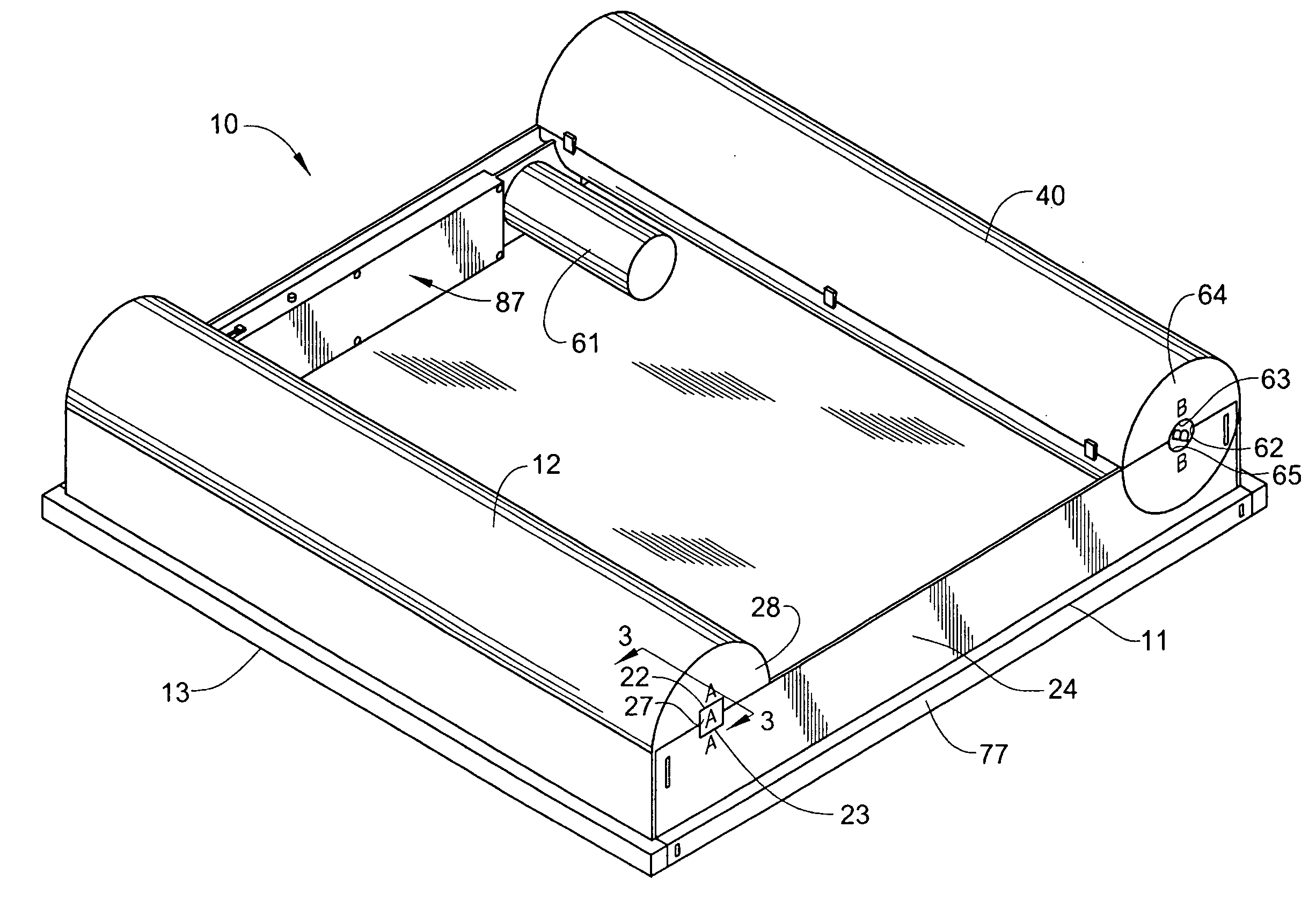
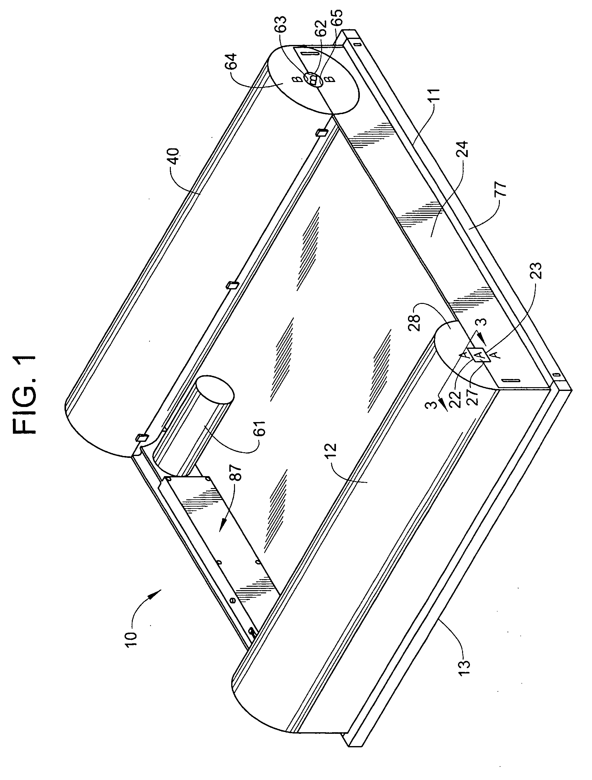
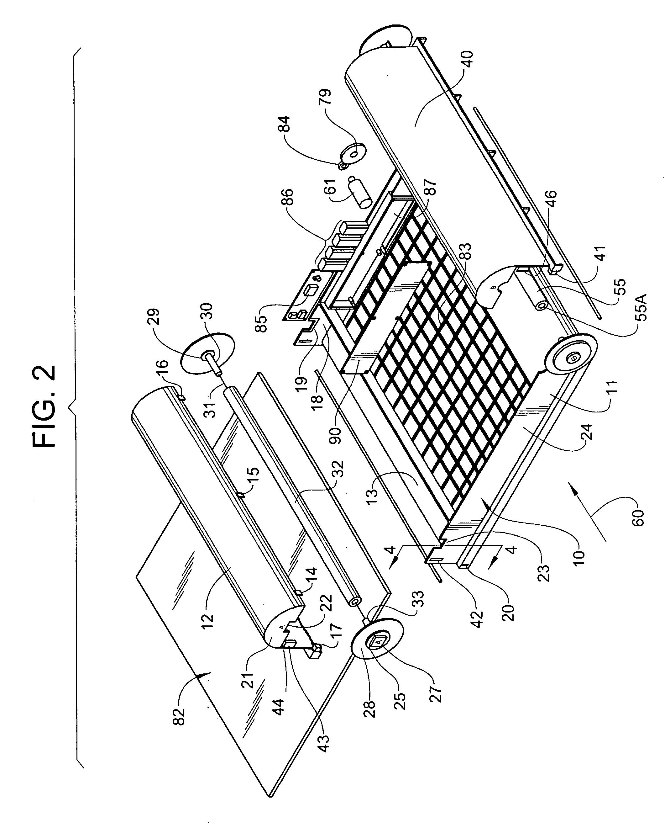
[0026]For a more complete appreciation of principles that characterize salient features of the invention attention is invited to FIG. 1 which shows the HVAC filter system 10. The system 10 is encased within a frame or box 11, preferably formed from a molded plastic. Prominent in the structure of the box 11 is a semi-cylindrical, hollow supply magazine 12 mounted on one end 13 of the box 11.

[0027]As best illustrated in FIG. 2 the supply magazine 12 has a group of detents of which only detents 14, 15, 16, 17 are shown in FIG. 2. The detents 14 through 17 are each, respectively engaged in corresponding detent couplings, of which only the detent coupling 20 on the box 11 is shown in FIG. 2. The detents 14 through 17 enable the supply magazine 12 to selectively “pop off” and snap fit to the box 11. The semicircular ends, of which only end 21 is shown in FIG. 2 is provided with one half of a rectangular journal 22 that meets with another rectangular journal half 23 formed in side 24 of th...


PUM

PropertyMeasurementUnit
diametersaaaaaaaaaa
diameteraaaaaaaaaa
radius of curvatureaaaaaaaaaa

Abstract

An air filter system for installation within the air inlet duct for an air conditioning system has a pair of mandrels that establish sufficient friction force when a web of fresh filter fabric is drawn from a supply roll to eliminate most undesirable wrinkles and slackness in the web. The “pop-off” feature of the fresh filter fabric supply and contaminated filter fabric storage magazines with a removable side enable a fresh roll of filter fabric to be installed in the system with minimal disagreeable effort. A peripheral step that protrudes from the base of the system enables the system to be adaptable to many existing air conditioner ducting structures. A back-up secondary filter, preferably treated with the activated carbon, permits less-than-particulate contamination, e.g. odors and noxious gases to be removed from the incoming air stream. Electrical circuits that control the sequential cycles for replacing the filter fabric webs, signals each progressive cycle and provide system condition cues are also described.

Description

CROSS-REFERENCES TO RELATED APPLICATIONS[0001]NoneFEDERALLY SPONSORED RESEARCH OR DEVELOPMENT[0002]NoneNAMES OF PARTNERS TO A JOINT RESEARCH AGREEMENT[0003]NoneREFERENCE TO “SEQUENCE LISTING”[0004]NoneBACKGROUND OF THE INVENTION[0005]This invention relates to a filter apparatus and method and, more particularly to a high volume air conditioner filter that provides up to one year of air filtration with simplified filter fabric replacement, better filter fabric tension control, improved filter cycle regulation, and the like.[0006]Although filters in high volume air conditioner systems (HVAC) should be replaced whenever the filter fabric becomes so obstructed with particulate matter that it significantly degrades the efficiency of the HVAC system, this generally disagreeable task is all to frequently overlooked. In most instances, the grating at the air inlet to the HVAC system must be removed, a large, rectangular frame supporting the used, dust laden filter fabric in a position gener...

Claims


Application Information

Patent Timeline
Patent Type & Authority Applications(United States)
IPC IPC(8): B01D46/20B01D46/46F24F8/108F24F8/158
CPCB01D46/0023F24F3/1603B01D46/44B01D46/18F24F8/10B01D46/62F24F8/108F24F8/158
Inventor LEWIS, TRAVIS
Owner LEWIS TRAVIS
Why Eureka
Try Eureka