Scrubber for fluid coker unit

Active Publication Date: 2010-04-01
EXXON RES & ENG CO
View PDF20 Cites 7 Cited by
  • Summary
  • Abstract
  • Description
  • Claims
  • Application Information

AI Technical Summary

Benefits of technology

[0007]We have now found that the rate of fouling in the scrubber section of a fluid coker unit may be reduced by providing baffles to reduce the local gas velocity of the cyclone outlet gases in the scrubber section of the unit. If the velocity of the gas jets from the cyclone outlets is reduced, entrainment of the circulating oil is reduced as the gas flow becomes more even and the temperature is reduced by improved contact between the hot gas jets and the cool circulating oil passing over the sheds. These baffles may be located either in or below the shed section of the scrubber, the objective in either case, being to reduce the local gas velocity in the scrubber, mainly in the shed section where the majority of the entrainment to the de-entrainment device takes place. By reducing the extent to which the hot gases from the cyclones bypass the sheds, two benefits result, fouling of the de-entrainment device is reduced and entrainment of circulating o

Problems solved by technology

In particular, fouling of the de-entrainment device, normally a grid, restricts the open flow paths in the grid and eventually leads to flooding and black oil entrainment.
A poorly operating scrubber can readily lead to poor product quality since this is determined in part by scrubber operation: heavy ends which contain metals, Conradson Carbon Residue (CCR) and, in the case of tar sand operations, fine clay solids, can enter the coker products, leading to problems in downstream units, particularly catalytic units such as hydrotreaters in which metals such as vanadium and nickel can poison the catalyst and entrained clay solids plug catalyst beds and cause high pressure drop.
The heavy

Method used


Image

  • Scrubber for fluid coker unit
  • Scrubber for fluid coker unit
  • Scrubber for fluid coker unit

Examples


Example

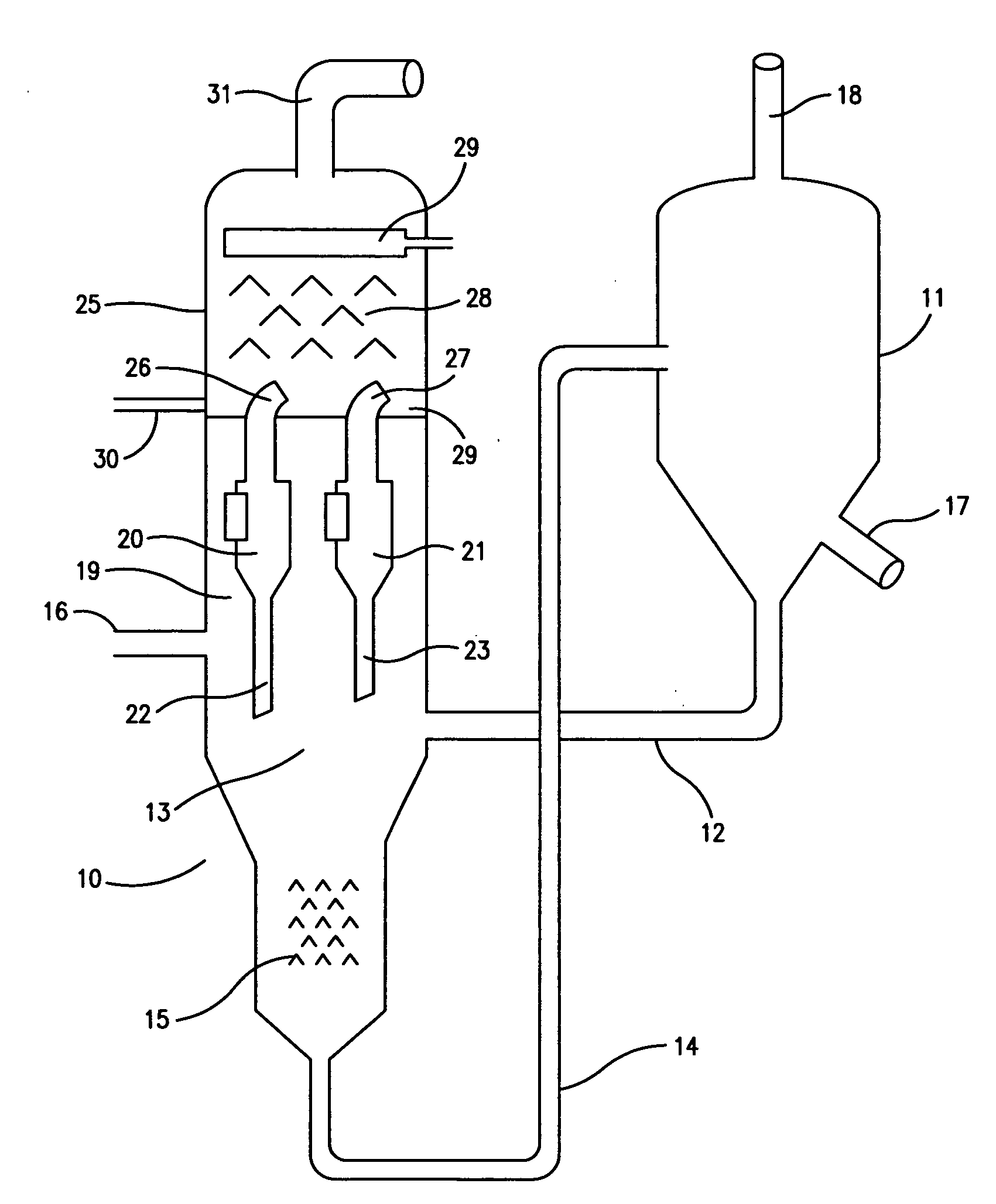
[0014]The present invention is applicable to fluid coking units, that is, to petroleum refinery process units in which a heavy oil feed is thermally cracked in the presence of a fluidized bed of coke particles which supply the heat required for the endothermic cracking reactions. Coke particles are continuously withdrawn from the bed and partly combusted in a separate coke burner vessel to raise the temperature of the particles which are then recirculated to the reactor vessel, as described above. Coke is also withdrawn from the unit as a fuel coke product or, alternatively, may be sent to a gasifier to be converted into refinery fuel gas, as in a Flexicoker fluid coking unit, as licensed by ExxonMobil Research and Engineering Company.

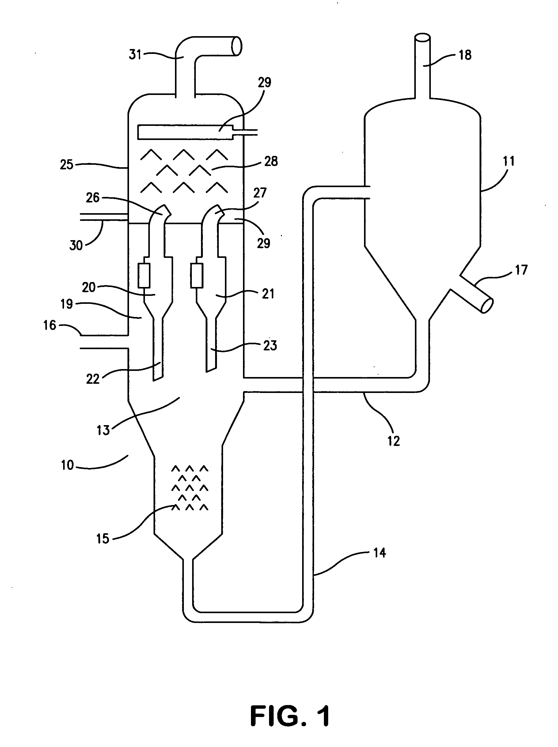
[0015]FIG. 1 shows a fluid coking unit with a reactor vessel 10 and a burner vessel 11 connected in the conventional manner by coke withdrawal conduit 14 which takes coke particles from the fluidized bed at location 13 in reactor 10 to burner vessel 11...


PUM

PropertyMeasurementUnit
Flow rateaaaaaaaaaa
Velocityaaaaaaaaaa

Abstract

Fouling in the scrubber section of a fluid coker unit is reduced by providing baffles to improve the uniformity of the gas flow profile in the scrubber by reducing the gas velocity of the cyclone outlet gases in the scrubber section of the unit. These baffles are located with the objective of reducing the rotational component of the gas flow in the scrubber created by the alignment of the gas outlets of the cyclones. The baffles are preferably located in the shed section of the scrubber and comprise upstanding perforated plates located at the periphery of the scrubber section to disrupt high velocity gas jets in the region of the interior wall of the scrubber.

Description

FIELD OF THE INVENTION[0001]The invention relates to fluidized bed coking, a thermal cracking process used in the refining of heavy petroleum oils to produce lower molecular weight, lower boiling range products.BACKGROUND OF THE INVENTION[0002]Fluidized bed coking (fluid coking), including its variant, the Flexicoking™ process, is a pyrolysis process used in the petroleum refining industry in which heavy petroleum fractions, typically the non-distillable residue (resid) from vacuum fractionation, are converted to lighter, more useful products by pyrolysis (coking) at elevated reaction temperatures, typically about 500 to 600° C. (approximately 900 to 1100° F.). In fluid coking, the heated heavy oil feed, mixed with atomizing steam, is admitted through a number of feed nozzles to a large vessel containing coke particles fluidized with steam and maintained at a temperature high enough to carry out the desired cracking reactions in the reactor section of the vessel. The feed components...

Claims


Application Information

Patent Timeline
IPC IPC(8): C10B55/10
CPCC10B55/10
Inventor MCKNIGHT, CRAIG A.HACKMAN, LARRY P.KNAPPER, BRIAN A.BULBUC, DANIELJONES, GEORGE B.TYLER, JONATHANKIEL, DARWIN
Owner EXXON RES & ENG CO
Why Eureka
Try Eureka