Multilayer metamaterial isolator

a metamaterial and isolator technology, applied in the field of isolating technology, microwave antenna arrays, and metamaterial isolators, can solve the problems of significant performance degradation, heat management, signal routing complexity, radiation pattern distortion and scan blindness, and achieve the effect of reducing cross-talk

Active Publication Date: 2010-04-01
RAYTHEON CO
View PDF17 Cites 36 Cited by
  • Summary
  • Abstract
  • Description
  • Claims
  • Application Information

AI Technical Summary

Benefits of technology

[0006]It is a further object of the subject invention to provide such an isolator which can be manufactured in a simpler fashion and at a lower cost.
[0009]It is a further object to provide such an isolator which enables a dense population of radiating elements in a more compact system.

Problems solved by technology

The result is often a larger size array which increases the complexity of signal routing, heat management, transportation of the array to its intended location, and the like.
Coupling (e.g., cross-talk) across adjacent radiating elements causes significant performance degradation including radiation pattern distortion and scan blindness.
The added steps associated with integrating individual unit cells adds to the cost and complexity of a system-level solution.
One disadvantage of such a technique is a narrow band and a solution useful for only very narrow element spacing.

Method used


Image

  • Multilayer metamaterial isolator
  • Multilayer metamaterial isolator
  • Multilayer metamaterial isolator

Examples


Embodiment Construction

[0043]Aside from the preferred embodiment or embodiments disclosed below, this invention is capable of other embodiments and of being practiced or being carried out in various ways. Thus, it is to be understood that the invention is not limited in its application to the details of construction and the arrangements of components set forth in the following description or illustrated in the drawings. If only one embodiment is described herein, the claims hereof are not to be limited to that embodiment. Moreover, the claims hereof are not to be read restrictively unless there is clear and convincing evidence manifesting a certain exclusion, restriction, or disclaimer.

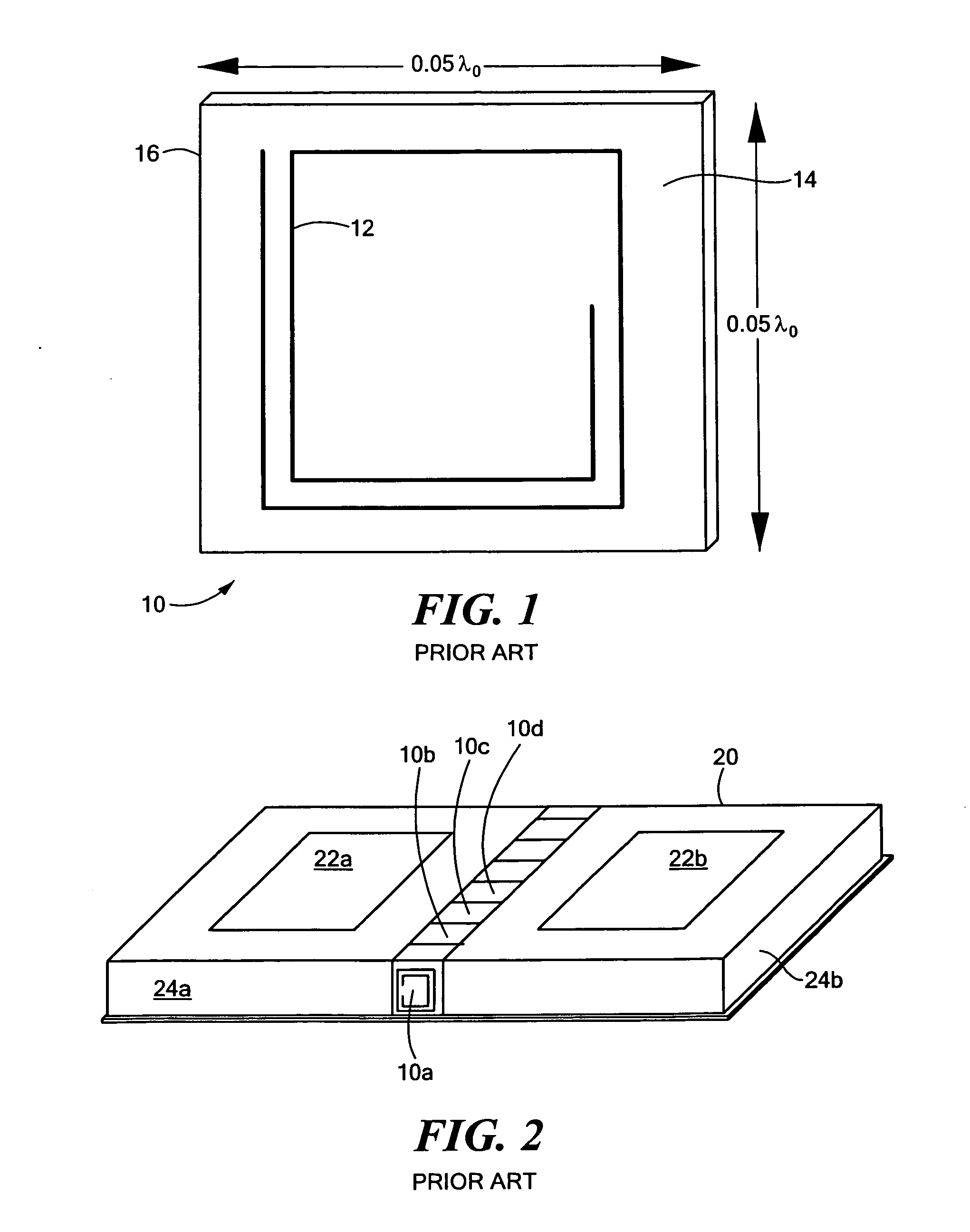
[0044]FIG. 1 shows a unit cell isolator 10 as discussed in Buell et al., “Metamaterial Insulator Enabled Superdirective Array,” IEEE Transactions on Antennas and Propagation, Vol. 55, No. 4 (April 2007). Metallic trace 12 is formed on face 14 of dielectric substrate 16. Thus, the trace is confined to one plane. As shown in ...


PUM

PropertyMeasurementUnit
unit cellsaaaaaaaaaa
sizeaaaaaaaaaa
separation distanceaaaaaaaaaa

Abstract

A multilayer metamaterial isolator and method of fabricating the same. A first layer or surface of a multilayer dielectric substrate includes a first leg of a first resonator loop. A second layer or surface of the multilayer dielectric substrate includes a second leg of the first resonator loop. A third leg of the first resonator loop extends through the multilayer dielectric substrate interconnecting the first and second legs of the first resonator loop.

Description

FIELD OF THE INVENTION[0001]The subject invention relates to isolation technology, microwave antenna arrays, and metamaterial isolators.BACKGROUND OF THE INVENTION[0002]Radar systems typically include a number of radiating elements often in an array. The recent trend is to increase the number of radiating elements in an attempt to attain better performance. There is a relationship between the number of radiating elements in a phased array and system performance with regard to gain, beam-steering, ECCM (electronic counter-counter measures, for example, anti-jamming), null-steering, and advanced beam forming capability. The result is often a larger size array which increases the complexity of signal routing, heat management, transportation of the array to its intended location, and the like. When the size of the array is reduced to address these concerns, the radiating elements are placed closer together. The result is an interaction between adjacent radiating elements. Coupling (e.g....

Claims


Application Information

Patent Timeline
Patent Type & Authority Applications(United States)
IPC IPC(8): H01P1/36H01P11/00
CPCH01P1/2005H01P1/365Y10T29/49016H01Q15/0086H01Q1/523
Inventor MORTON, MATTHEW A.IMHOLT, JIYUN C.BUELL, KEVIN
Owner RAYTHEON CO
Why Eureka
Try Eureka