
Polarizing fiber, polarizer, polarizing plate, laminated optical film, and image display

a technology of laminated optical film and polarizing fiber, which is applied in the direction of polarizing elements, optical elements, instruments, etc., can solve the problems of insufficient strength of birefringent fibers, difficult to arrange polarizing fibers and birefringent fibers evenly in parallel to the longitudinal direction, etc., and achieves larger polarizing performance. , the effect of diffused or scattered reflection

Inactive Publication Date: 2010-04-01
NITTO DENKO CORP
View PDF14 Cites 5 Cited by
  • Summary
  • Abstract
  • Description
  • Claims
  • Application Information

AI Technical Summary

Benefits of technology

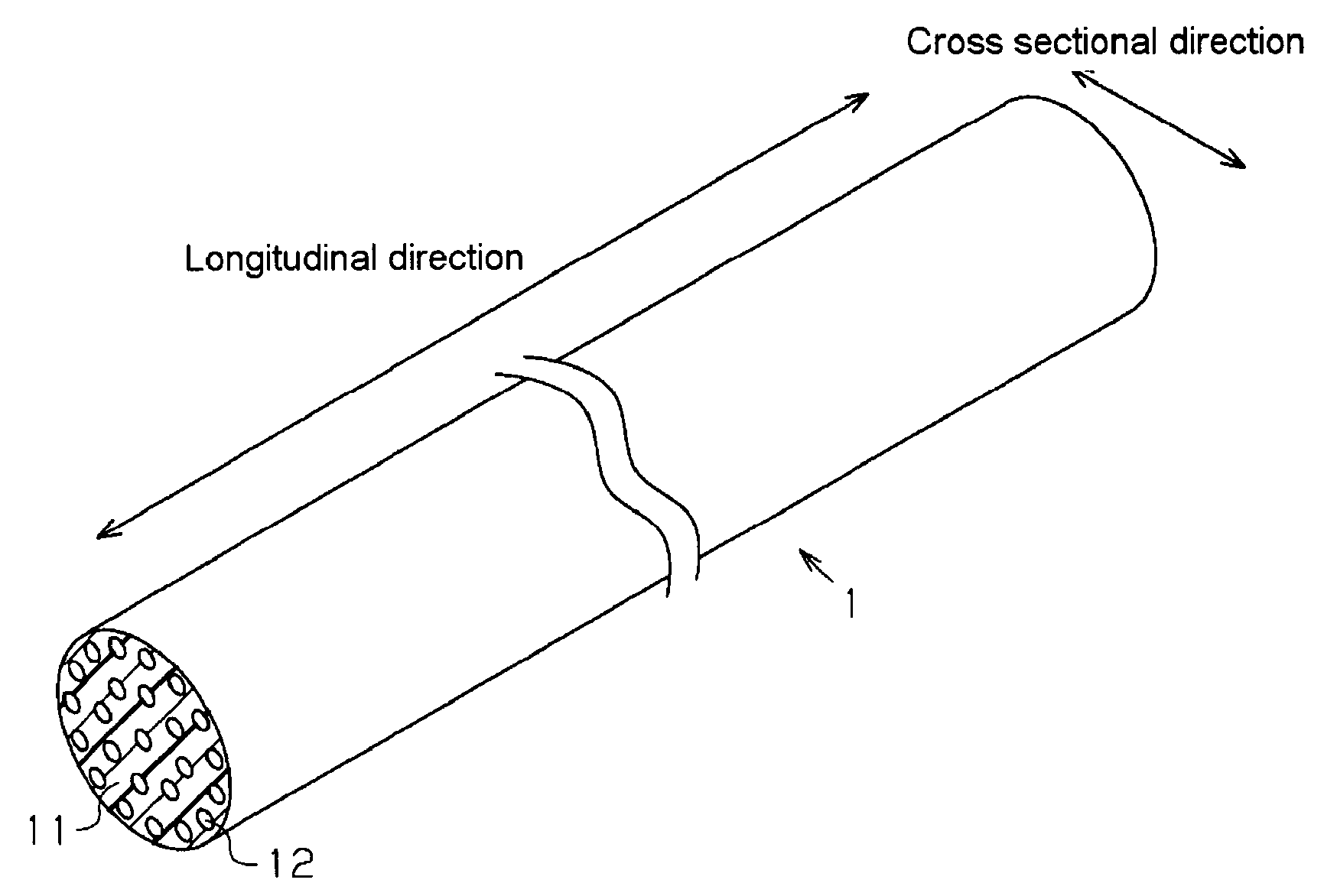
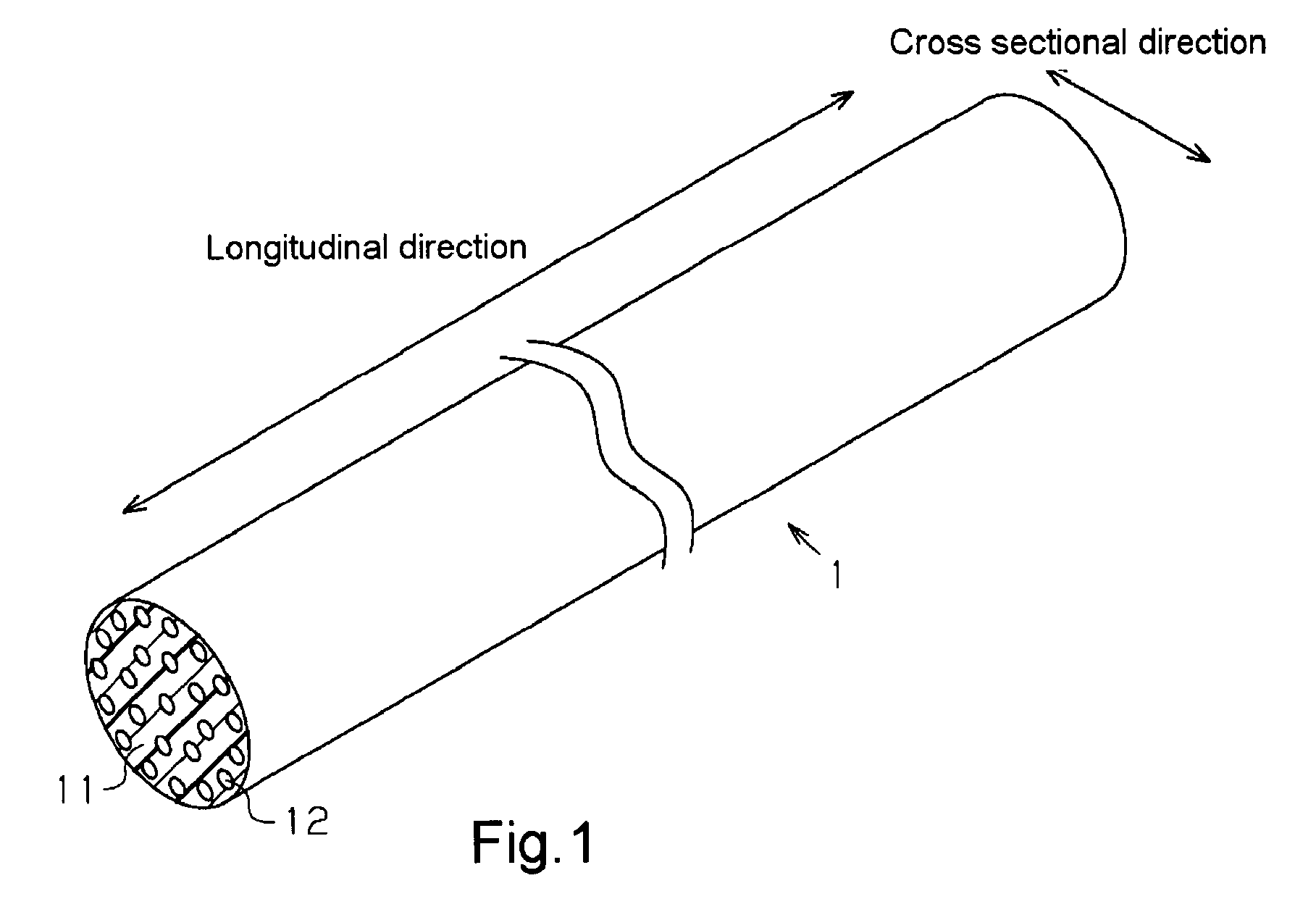
[0016]A first object of the present invention is to provide a polarizing fiber that makes it possible to form easily a birefringent fiber having a thickness (diameter) giving a good scattering efficiency and further exhibits the same effect as a case where a polarizing fiber and a birefringent fiber are evenly arranged in parallel to the longitudinal direction thereof.
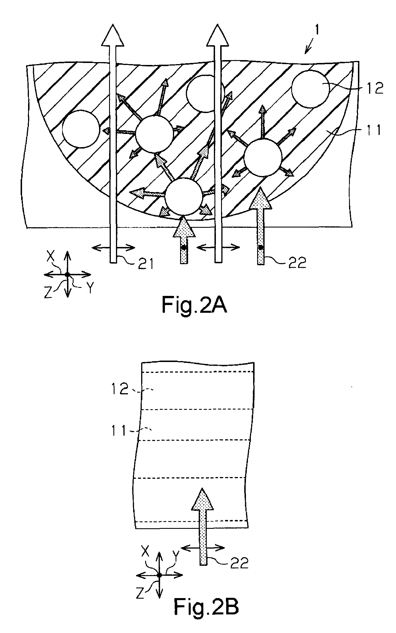
[0037]In the preferable polarizer, the difference Δn3 between the refractive index of the sea component in the direction perpendicular to the longitudinal direction and that of the isotropic material is 0.02 or less; therefore, polarized light in the direction perpendicular to the longitudinal direction can be restrained from being reflected, diffused, or scattered on the interface between the sea component and the isotropic material. Thus, the polarizer becomes high in transmittance, and easily transmits polarized light in the direction perpendicular to the longitudinal direction.

Problems solved by technology

However, when the birefringent fiber in the technique of Patent Document 5 is formed into a thickness (diameter) giving a good scattering efficiency, the strength of the birefringent fiber becomes insufficient.
Also, in the technique of Patent Document 5, it is also difficult to arrange the polarizing fiber and the birefringent fiber evenly in parallel to the longitudinal direction.

Method used


Image

  • Polarizing fiber, polarizer, polarizing plate, laminated optical film, and image display
  • Polarizing fiber, polarizer, polarizing plate, laminated optical film, and image display
  • Polarizing fiber, polarizer, polarizing plate, laminated optical film, and image display

Examples


example 1

Polarizing Fiber A

[0106]A nozzle for sea-island composite fiber spinning was used to extrusion-mold an island component material and a sea component material described below, thereby producing a polarizing fiber A.

[0107]The used island component material was a propylene-excessive ethylene-propylene copolymer having a melting point of 138° C. and a melt flow index of 25 g / 10 min (trade name: “OX1066A”, manufactured by Japan Polypropylene Corp.).

[0108]The used sea component material was a material obtained by immersing resin pellets of an ethylene-vinyl alcohol copolymer having a melting point of 181° C. and a melt flow index of 12 g / 10 min (trade name: “SOANOL (transliterated) DC3212B”, manufactured by Nippon Synthetic Chemical Industry Co., Ltd.) in a 2% water solution of a dichroic dye (trade name: “Congo Red”, manufactured by Kishida Chemical Co., Ltd.) at 90° C. for 4 hours, washing the pellets with water, and then drying the pellets sufficiently in a vacuum drier.

[0109]The used ...

example 2

Polarizing Fiber B

[0121]A polarizing fiber B was produced by using the same materials and producing method as in Example 1 except that a dye (trade name: “DIRECT GREEN 85”) manufactured by Mitsubishi Chemical Corp. was used as a dichroic dye. The producing method and so on in Example 2 were the same as in Example 1; thus, description thereof is omitted. Moreover, measured results of the diameters, the island number and the refractive indexes were also the same; thus, description thereof is also omitted.

example 3

Polarizing Fiber C

[0122]A nozzle for core-sheath structure fiber spinning was used to extrusion-mold an island component material and a sea component material described below, thereby producing a polarizing fiber C. The nozzle for core-sheath structure fiber spinning is a nozzle for sea-island composite fiber spinning wherein the island number is 1. In the following description, the term “island component” will be used instead of the term “core component”, and the term “sea component” will be used instead of the term “sheath component” unless especially necessitated.

[0123]The used island component material was a crystalline polypropylene having a melting point of 161° C. and a melt flow index of 26 g / 10 min (trade name: “SA03A”, manufactured by Japan Polypropylene Corp.).

[0124]The used sea component material was the same material as the sea component material described in the Example 1.

[0125]A polarizing fiber was obtained by use of the nozzle for core-sheath structure fiber spinnin...


PUM

PropertyMeasurementUnit
diameteraaaaaaaaaa
refractive indexaaaaaaaaaa
diameteraaaaaaaaaa

Abstract

As the polarizing fiber of the present invention, the cross sectional form perpendicular to the longitudinal direction has a sea-island structure, and the cross sectional form is continuously made up in the longitudinal direction. A resin (sea component) that constitutes the sea region of the sea-island structure comprises a dichroic dye, and a resin (island component) that constitutes the island regions of the sea-island structure is a transparent resin.The polarizing fiber of the present invention may be used as a forming material of a polarizer, for example. By using the above polarizing fiber, a polarizer wherein unevenness of the transmittance is small and cracks are less generated may be formed.

Description

TECHNICAL FIELD[0001]The present invention relates to a polarizing fiber, a polarizer, a polarizing plate, a laminated optical film, and an image display. More specifically, the present invention relates to a polarizing fiber preferably used to produce a polarizer wherein unevenness of the transmittance is small and cracks are less generated.BACKGROUND ART[0002]In general, liquid crystal displays have a liquid crystal panel wherein a laminated optical film comprising a polarizer is adhered onto each of two surfaces of a liquid crystal cell, and the liquid crystal cell is made of a liquid crystal material sandwiched between two glass plates. As this polarizer, there is generally used a drawn film obtained by dyeing a polyvinyl alcohol (PVA) based film with iodine or the like, and then drawing the film uniaxially. This polarizer is a polarizer exhibiting absorption dichroism.[0003]As the display performance of liquid crystal displays has been improved in recent years, polarizers which...

Claims


Application Information

Patent Timeline
Patent Type & Authority Applications(United States)
IPC IPC(8): G02B5/30
CPCD01D5/36D01F8/06G02B5/30G02B5/3025G02B27/28D01F8/10D01F8/04
Inventor MIYATAKE, MINORUNISHIMURA, AKINORISHINAGAWA, MASASHIIWAKAWA, YASUKO
Owner NITTO DENKO CORP
Learn More