Method for cleaning photomask-related substrate, cleaning method, and cleaning fluid supplying apparatus

a technology of photomasks and substrates, applied in the direction of cleaning processes, cleaning apparatus, liquid cleaning, etc., can solve the problems of particle generation after drying substrates, excessively fine foreign matter and cloudiness, and increase the time of pure water being so as to reduce the amount of time during which pure water is exposed to air or the like, and the effect of removing sulfate ions efficiently

Active Publication Date: 2010-04-08
SHIN ETSU CHEM IND CO LTD
View PDF9 Cites 14 Cited by
  • Summary
  • Abstract
  • Description
  • Claims
  • Application Information

AI Technical Summary

Benefits of technology

[0027]In particular, it is possible that the photomask-related substrate to be cleaned with the pure water is a photomask-related substrate treated with sulfuric acid or a material containing sulfate.
[0028]As described above, since the photomask-related substrate to be cleaned with the pure water is first treated with sulfuric acid or a material containing sulfate, it is possible to remove an organic substance or the like on the surface of the photomask-related substrate by cleaning inexpensively and effectively.
[0029]The cleaning method of the invention is also effective for such a photomask-related substrate treated with sulfuric acid or a material containing sulfate, and, even when a sulfate ion is attached to the substrate surface due to a residue of sulfuric acid or the like, it is possible to remove the sulfate ion efficiently.
[0030]At this time, it is possible that, when cleaning with the pure water is performed, the cleaning is performed by pouring flowing pure water on the photomask-related substrate.
[0031]It is preferable that the pure water subjected to the deaerating step is used for cleaning after being exposed to the air or other gases as little as possible after deaeration. Therefore, by performing cleaning by using flowing pure water as described above, the amount of time during which the pure water is exposed to the air or the like is reduced, making it possible to make good use of the effect obtained by removal of dissolved gas by deaeration, the effect of removing the sulfate ion efficiently, and achieve a higher degree of cleaning efficiency.
[0032]Moreover, it is preferable that the deaerating step is performed by using a gas-liquid separation film.

Problems solved by technology

However, as the photomask has come to be used for exposure of an extremely fine pattern, even extremely fine foreign matter and haze (cloudiness) become a defect.
However, the use of a high-energy beam such as ArF excimer laser light as exposure light causes a phenomenon in which a sulfate ion and an ammonium ion remaining on the substrate form an ammonium sulfate microcrystal, and this microcrystal becomes a particle and is counted as a defect.
Such a phenomenon has become a problem (for example, see Japanese Unexamined Patent Publication (Kokai) No. 2005-202135).
However, even when cleaning is performed by using heated pure water as described above, a particle is generated after drying the substrate.
On the other hand, even when the above-described multistage cleaning is performed, the obtained substrate is not always unconditionally clean, and fine foreign matter is generated at significant frequency.

Method used


Image

  • Method for cleaning photomask-related substrate, cleaning method, and cleaning fluid supplying apparatus
  • Method for cleaning photomask-related substrate, cleaning method, and cleaning fluid supplying apparatus
  • Method for cleaning photomask-related substrate, cleaning method, and cleaning fluid supplying apparatus

Examples


first embodiment

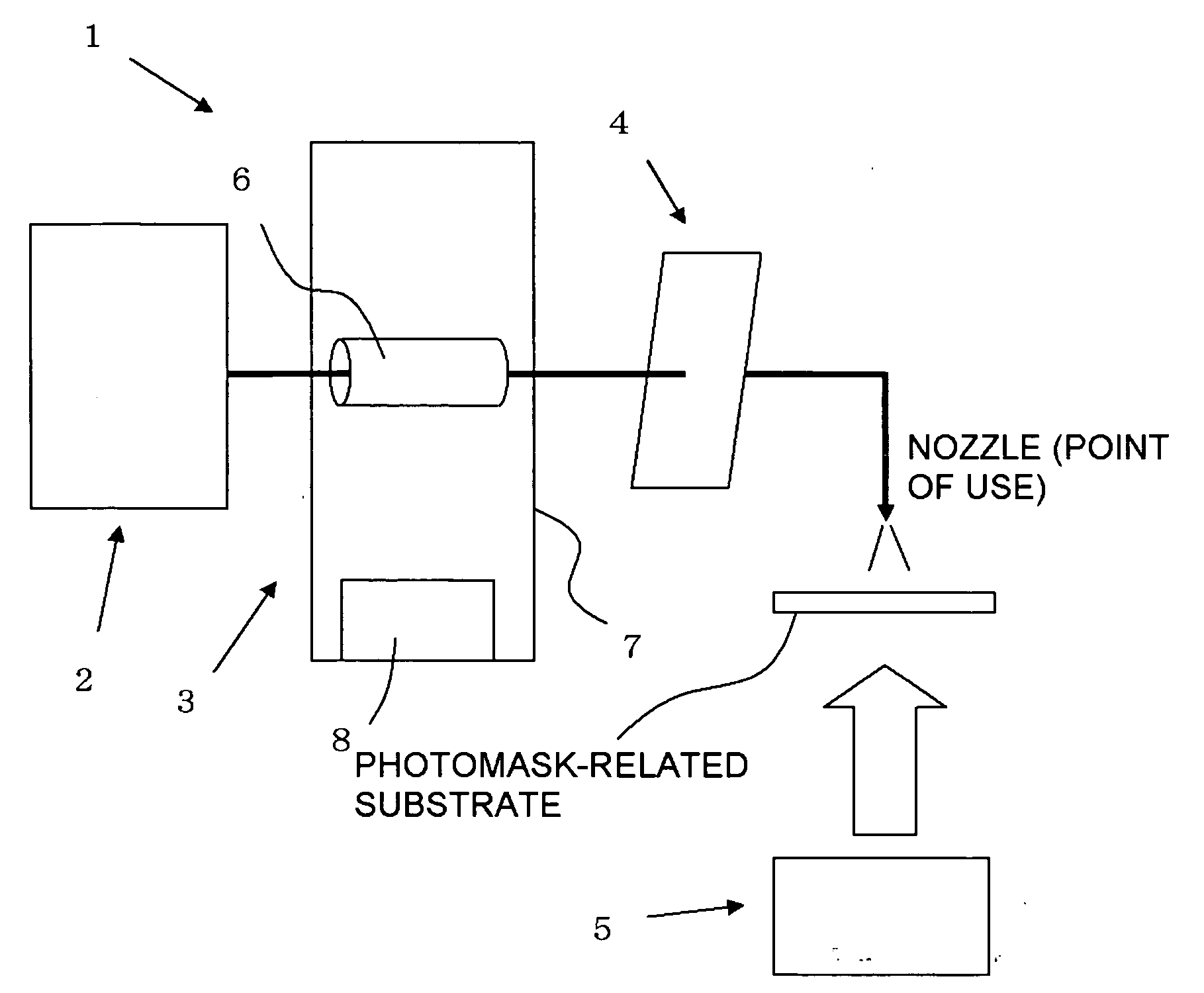
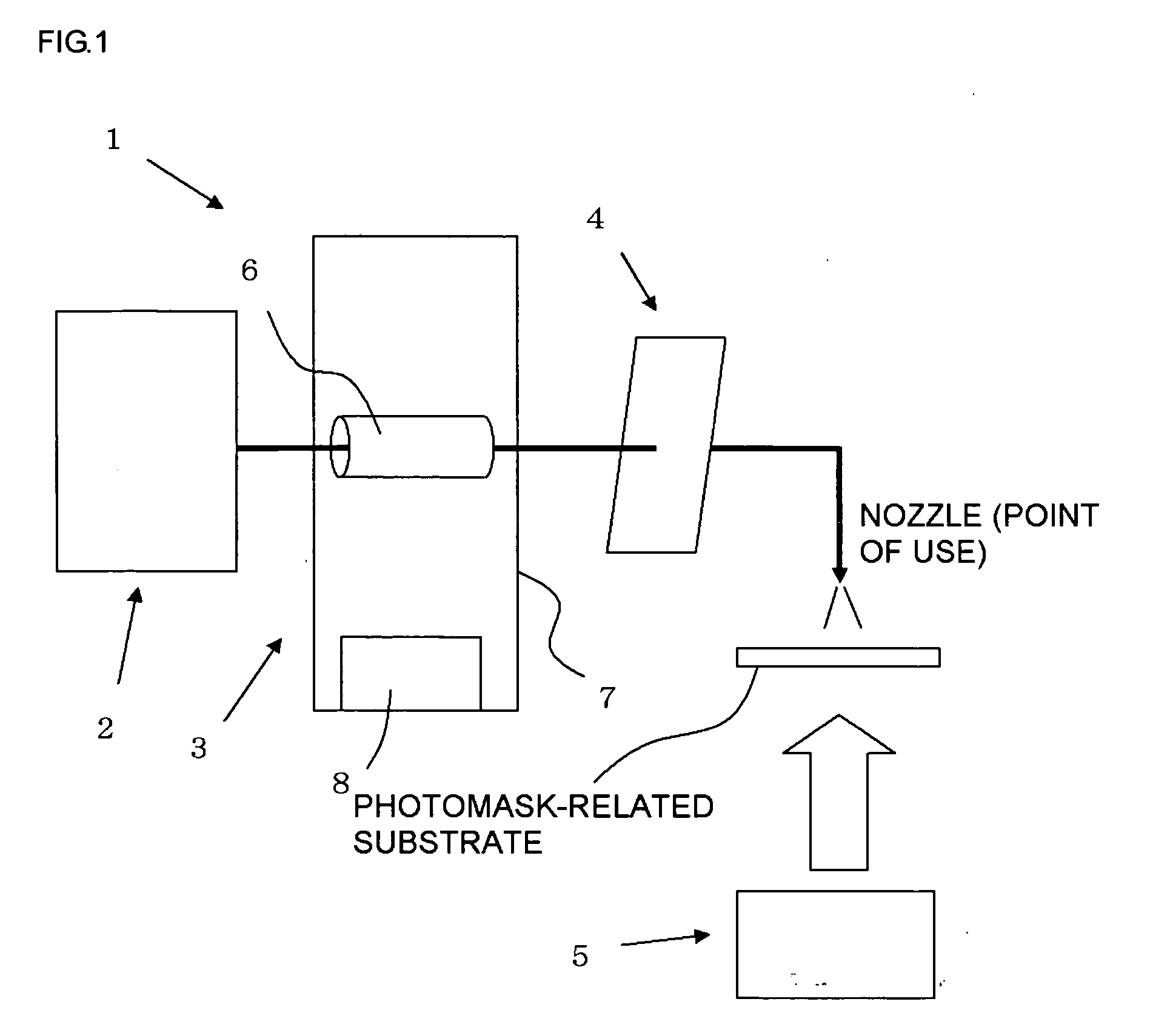
[0165]In FIG. 3, an outline of an example of the cleaning fluid supplying apparatus of the invention is shown. Incidentally, a cleaning apparatus 110 disposed downstream of a cleaning fluid supplying apparatus 101 and a substrate 112 to be cleaned by a cleaning fluid sprayed from a nozzle 111 (point of use) of the cleaning apparatus are also shown.

[0166]Incidentally, the substrate 112 to be cleaned may be, for example, a transparent substrate for a photomask, a photomask blank, a photomask blank production intermediate, and a photomask which require precise cleaning. It goes without saying that the cleaning fluid supplying apparatus of the invention can be applied to cleaning of objects other than those described above.

[0167]Moreover, when the cleaning fluid is, for example, ultrapure water, the equipment for producing ultrapure water is usually provided with an apparatus for removing gas which may be generated during a process such as UV sterilization to the outside of the system, ...

second embodiment

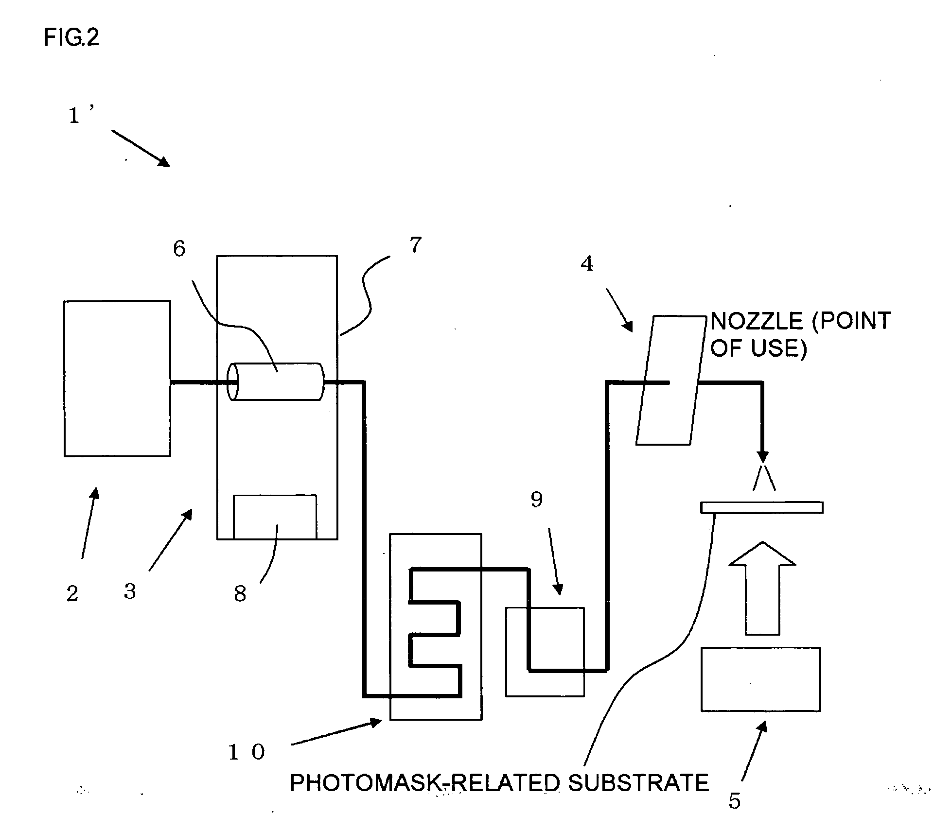
[0185]In a case shown in FIG. 4, a cleaning fluid supplying apparatus 201 of the invention in accordance with another embodiment is shown. In FIG. 4, a supply pipe 206 and a discharge pipe 207 are connected directly to the upper surface of a filter housing 205.

[0186]At this time, as shown in FIG. 4(A), the supply pipe 206 and the discharge pipe 207 can be connected in such a way that a height position of an inlet 208a of the supply pipe 206 and a height position of an inlet 208b of the discharge pipe 207 are on the same level by horizontally placing a housing 202 and the filter housing 205 of the cleaning fluid supplying apparatus 201, for example.

[0187]On the other hand, as shown in FIG. 4(B), the supply pipe 206 and the discharge pipe 207 can also be connected in such a way that the height position of the inlet 208b of the discharge pipe 207 is above the height position of the inlet 208a of the supply pipe 206 by placing the housing 202 and the filter housing 205 of the cleaning f...

third embodiment

[0189]In FIG. 5, a cleaning fluid supplying apparatus 301 of the invention in accordance with still another embodiment is shown.

[0190]In a case shown in FIG. 5, a supply pipe 306 and a discharge pipe 307 are connected directly to a side surface of a filter housing 305. Also in this case, it is preferable that the supply pipe 306 and the discharge pipe 307 be connected in such a way that a height position of an inlet 308b of the discharge pipe 307 is above the height position of an inlet 308a of the supply pipe 306.

[0191]Moreover, a bubble removal pipe 313 is connected to a side surface of a housing 302, the side surface opposite to the side surface in which a cleaning fluid inlet 303 is provided.

[0192]Up to this point, the embodiments of the cleaning fluid supplying apparatus of the invention have been described with examples; however, the cleaning fluid supplying apparatus of the invention is not limited to those embodiments. The cleaning fluid supplying apparatus of the invention ...


PUM

PropertyMeasurementUnit
temperatureaaaaaaaaaa
sizeaaaaaaaaaa
lengthaaaaaaaaaa

Abstract

Provided is a method for cleaning a photomask-related substrate, the method in which, when a photomask-related substrate contaminated by a sulfate ion, the photomask-related substrate being selected from a substrate for a photomask, a photomask blank, a photomask, and a production intermediate thereof, is cleaned with pure water, a deaerating step of removing dissolved gas by deaeration is performed in advance on the pure water used for cleaning. Moreover, provided is a method for cleaning a substrate to be cleaned by supplying a cleaning fluid to a cleaning apparatus, the method in which, when the substrate to be cleaned is cleaned by filtering the cleaning fluid with a filter for removing foreign matter and supplying the filtered cleaning fluid to the cleaning apparatus through a supply pipe, at least, prior to a supply of the filtered cleaning fluid to the cleaning apparatus, the filtered cleaning fluid is discharged to the outside of a system through a discharge pipe, and then the filtered cleaning fluid is supplied to the cleaning apparatus through the supply pipe. As a result, provided is a cleaning method that can increase cleaning efficiency for a sulfate ion in a simple and easy way and can reduce the generation of minute foreign matter extremely when, in particular, a photomask-related substrate selected from a substrate for a photomask, a photomask blank, a photomask, and a production intermediate thereof is cleaned.

Description

BACKGROUND OF THE INVENTION[0001]1. Field of the Invention[0002]The present invention relates to a method for cleaning a photomask-related substrate selected from a substrate for a photomask, a photomask blank, a photomask, and a production intermediate thereof, and, more particularly to removal of a sulfate ion attached to the surface of a photomask-related substrate and inhibition of the generation of a particle.[0003]2. Description of the Related Art[0004]A photomask used for wide applications including production of a semiconductor integrated circuit such as an IC, an LSI, or a VLSI, and other is basically obtained by processing a light shielding film of a photomask blank having the light shielding film formed of a thin film containing metal or a metal compound, the light shielding film formed on a translucent substrate (a substrate for a photomask), into a predetermined light shielding film pattern by using electron-beam photolithography or the like.[0005]In recent years, patte...

Claims


Application Information

Patent Timeline
Patent Type & Authority Applications(United States)
IPC IPC(8): B08B3/00
CPCY10S134/902G03F1/82
Inventor NUMANAMI, TSUNEO
Owner SHIN ETSU CHEM IND CO LTD
Why Eureka
Try Eureka