Supercharge Your Innovation With Domain-Expert AI Agents!

Ion current measurement device

a measurement device and current technology, applied in the field of measurement devices, can solve the problems of serious public safety problems, easy fire of phosphorous ion residuals, and residual pilling problems, and achieve the effect of reducing the phenomenon of residual coating

Active Publication Date: 2010-04-08
UNITED MICROELECTRONICS CORP
View PDF2 Cites 1 Cited by
  • Summary
  • Abstract
  • Description
  • Claims
  • Application Information

AI Technical Summary

Benefits of technology

[0007]Accordingly, the present invention is to provide an ion current measurement device capable of reducing the residual coating phenomenon happening in the ion collecting cup.
[0008]The present invention is further to provide a replaceable liner element capable of extending the life time of the ion current measurement device.
[0028]In the present invention, since the replaceable liner, disposed insider the ion collecting cup, covers the continuous inner sidewall directly blocking the ions, the problems, such as residual pilling or cleaning difficulty, caused by the residual coating on the continuous inner sidewall of the ion current measurement device due to the gases produced by the blocked ions can be overcome. Further, the cleanliness of the ion collecting cup can be well maintained and the risk for cleaning the ion collecting cup is decreased.

Problems solved by technology

Hence, the residual pilling problem happens.
Furthermore, because of the huge amount of phosphorous ion residual coating on the inner wall of the ion current measurement device, it is easily to fire the phosphorous ion residual during the cleaning process, such as vacuuming or polishing.
Thus, the cleaning process for cleaning the inner wall of the ion current measurement device induces serious public security problem.

Method used


Image

  • Ion current measurement device
  • Ion current measurement device
  • Ion current measurement device

Examples


Embodiment Construction

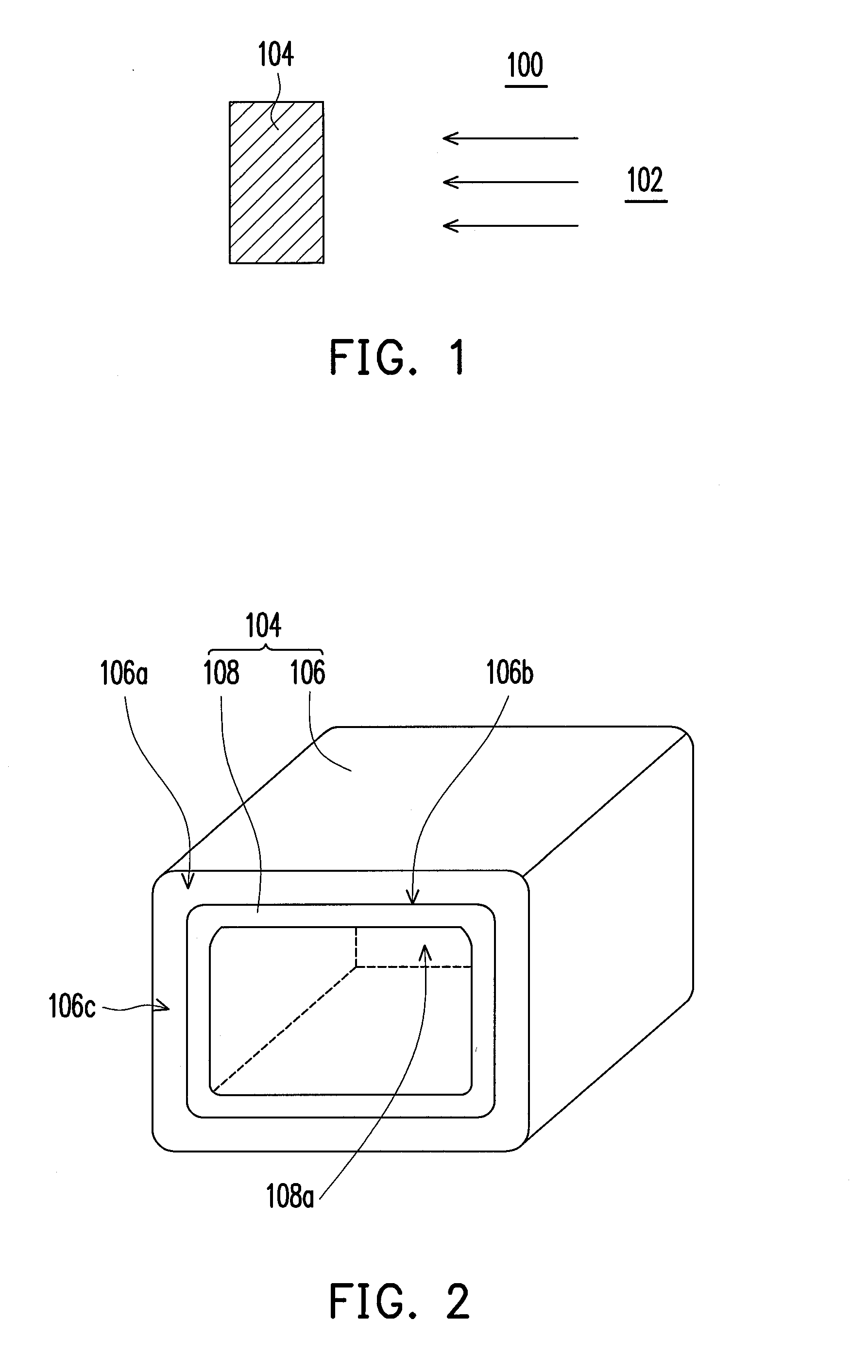
[0035]FIG. 1 is a schematic drawing showing a tool equipped with an ion current measurement device. As shown in FIG. 1, in a tool 100 equipped with an ion source device 102, an ion current measurement device 104 is provided. Before the later performed process, such as ion implantation process, is performed, the ion current measurement device 104 is used to measure the actual ion current within the tool 100. The tool 100 can be, for example but not limited to, an ion implantation machine.

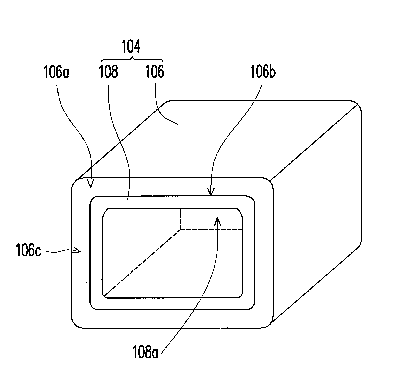
[0036]FIG. 2 is a three-dimensional view showing an ion current measurement device according to one embodiment of the present invention. As shown in FIG. 1 and FIG. 2, the aforementioned ion current measurement device 104 comprises an ion collecting cup 106 and a replaceable liner 108. It should be noticed that the ion collecting cup 106 is disposed in the tool 100 and the arrangement of the ion collecting cup 106 is that the cup opening 106a of the ion collecting cup 106 faces the ion source device ...


PUM


Abstract

The invention provides an ion current measurement device for a tool having an ion source. The ion current measurement device comprises an ion collecting cup and a replaceable liner. The ion collecting cup is disposed in the tool and the ion collecting cup possesses a cup opening facing the ion source. The replaceable liner is disposed in the ion collecting cup and the replaceable liner entirely covers a continuous inner sidewall of the ion collecting cup.

Description

BACKGROUND OF THE INVENTION[0001]1. Field of Invention[0002]The present invention relates to a measurement device. More particularly, the present invention relates to an ion current measurement device.[0003]2. Description of Related Art[0004]Before the ion related process, such as ion implantation process, is performed, it is usually to measure the ion current of the ion beam produced by the ion source to confirm the actual ion current amount of the later performed ion related process. Currently, the most used ion current measurement device is Faraday housing (as known as Faraday cup).[0005]Since the ion current measurement device collects total ions of the ion beam from the ion source in a time period for further calculating the actual ion current, the ions (or ion beam) is blocked inside the ion current measurement device before the ions can reach the target. And the blocked ions (ion beam) produce gases and further induce residual coating inside the ion current measurement device...

Claims


Application Information

Patent Timeline
IPC IPC(8): G01N27/00G21F5/00
CPCH01J37/244H01J37/3171H01J2237/24564H01J2237/24405H01J2237/022
Inventor CHEN, JUI-FANGCHANG, CHENG-HUNGCHEN, CHUNG-JUNGKO, CHIEN-KUOYAO, CHI-CHUN
Owner UNITED MICROELECTRONICS CORP
Features
  • R&D
  • Intellectual Property
  • Life Sciences
  • Materials
  • Tech Scout
  • Unparalleled Data Quality
  • Higher Quality Content
  • 60% Fewer Hallucinations
Learn More