

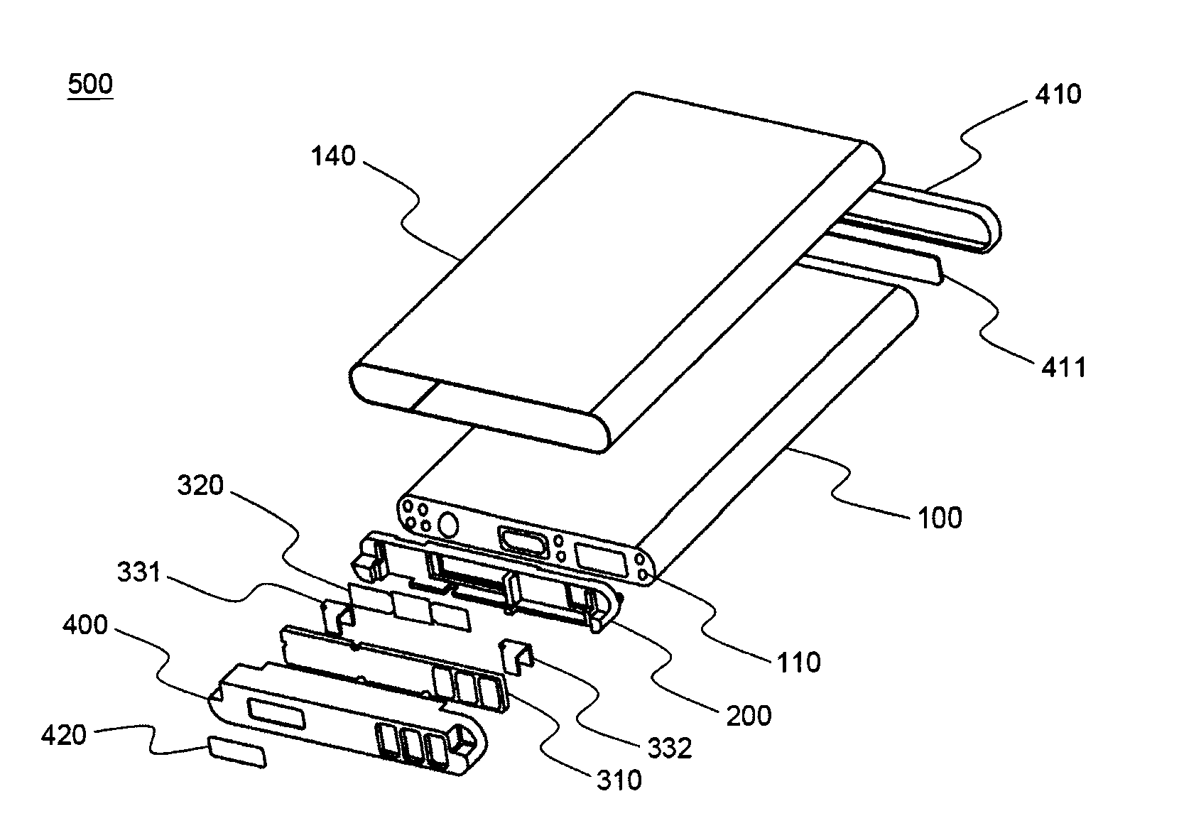
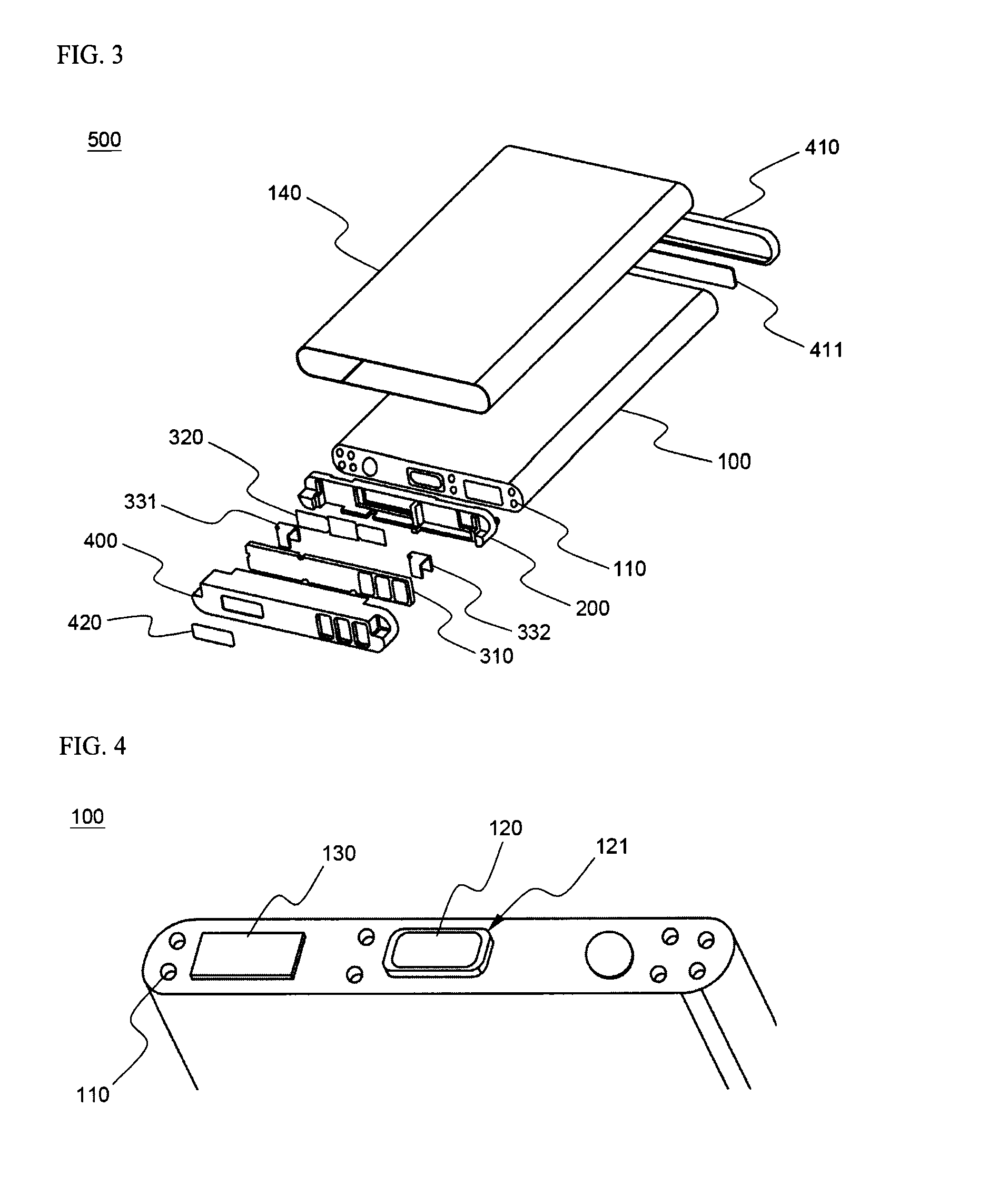
Secondary battery pack
a secondary battery and battery pack technology, applied in the direction of batteries, sustainable manufacturing/processing, cell components, etc., can solve the problems of high cost, high cost, and high safety of lithium secondary batteries, and achieve the effect of maximizing this
- Summary
- Abstract
- Description
- Claims
- Application Information
AI Technical Summary
Benefits of technology
Problems solved by technology
Method used
Image

Examples
example 1
[0074]Slurry, prepared by adding lithium cobalt oxide, PVdf, and a conducting agent in a well-known composition ratio, was coated on an aluminum current collector to manufacture cathodes. Slurry, prepared by adding graphite, PVdf, and a conducting agent in a well-known composition ratio, was coated on a copper current collector to manufacture anodes.
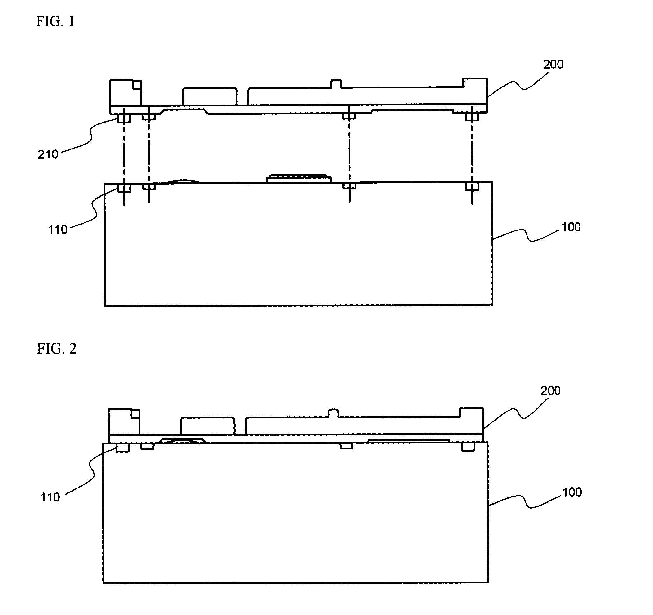
[0075]Separators, having a size slightly greater than that of the cathodes and the anodes, were disposed respectively between the cathodes and the anodes to manufacture an electrode assembly. The manufactured electrode assembly was mounted in a prismatic aluminum battery container. A battery container cover was mounted to the battery container, and an electrolyte was injected into the battery container through an injection port, to manufacture a battery cell.
[0076]Coupling protrusions, formed at the bottom of an insulative mounting member, were inserted into coupling grooves, formed at the top of the battery cell having a structure as sh...
experimental example 1
[0079]Bending tests were carried out on 20 battery packs manufactured according to
[0080]Example 1 and 20 battery packs manufactured according to Comparative example 1, to measure the coupling strength between the battery cell of each battery and the insulative mounting member coupled to the battery cell (See FIGS. 13 and 14). Specifically, load applied to the middle of each battery pack was gradually increased, while the top cap and the bottom cap of each battery pack were fixed. The magnitudes of the load when the battery packs broke are indicated in Table 1 below.
TABLE 1Breaking load (kgf)Example 1Comparative example 1Less than 250625 to 3001230 to 350245 to 509—50 to 5510—More than 551—
[0081]As can be seen from Table 1 above, the coupling force of the battery packs manufactured according to Example 1 was greatly improved as compared to the coupling force of the battery packs manufactured according to Comparative example 1.
[0082]Specifically, when load of less than 35 kgf was appl...
experimental example 2
[0083]Twist tests were carried out on 20 battery packs manufactured according to Example 1 and 20 battery packs manufactured according to Comparative example 1, to measure the coupling strength between the battery cell of each battery and the insulative mounting member coupled to the battery cell (See FIGS. 15 and 16). Specifically, the bottom cap of each battery pack was twisted in one direction, while the top cap of each battery pack was fixed. At this time, the twisting force was gradually increased to manufacture the magnitudes of the twisting force when the separation between each battery cell and the insulative mounting member coupled to the top of each battery cell occurred. The magnitudes of the twisting force when the battery packs broke are indicated in Table 2 below.
TABLE 2Breaking torque (kg · cm)Example 1Comparative example 1Less than 2001520 to 250525 to 300—30 to 350—35 to 407—40 to 4511—More than 452—
[0084]As can be seen from Table 2 above, the coupling force of the ...
PUM
 Abstract
Description
Claims
Application Information