High speed laser scribing method of fragile material

a laser scribing and fragile material technology, applied in glass making apparatus, manufacturing tools, instruments, etc., can solve the problems of difficult mechanical cutting of tempered glass used in architecture, weakening the mechanical strength of glass, and not free from various kinds of problems, so as to accelerate thermal stress scribing of glass

Inactive Publication Date: 2010-04-15
GLOBALY TECH CO LTD
View PDF23 Cites 89 Cited by
  • Summary
  • Abstract
  • Description
  • Claims
  • Application Information

AI Technical Summary

Benefits of technology

[0029]Furthermore, it is possible to accelerate thermal stress scribing of the glass or the fragile materials by cooling a point which is backwardly located on the laser beam scanning line and apart from backward end of the heating area heated by the irradiating l

Problems solved by technology

The cutting of fine glass plate used in flat panel displays which are in liquid crystal (hereafter abbreviated as liquid crystal TV or plasma TV sets is presently performed using the conventional mechanical method, which is not free from the various kinds of problems such as the necessity of polishing, existence of micro-crack layer, etc.
Tempered glass used in architecture is difficult to cut mechanically and requires a new processing method.
The second is the generation of micro-crack in the processed area, which weakens the mechanical strength of glass.
The rapid local heating invites random and irregular but mostly radially distributed cracks, which cannot realize a controlled straight line scribing in the desired direction.
When the tensile stress exceeds a cleavage toughness, whic

Method used


Image

  • High speed laser scribing method of fragile material
  • High speed laser scribing method of fragile material
  • High speed laser scribing method of fragile material

Examples


first exemplary embodiment

1. First Exemplary Embodiment

[0048]FIG. 6 is a schematic diagram explaining high speed laser scribing method of a glass plate according to the present invention. FIG. 7A to 7C shows a laser beam intensity distribution figure in a first exemplary embodiment according to the present invention.

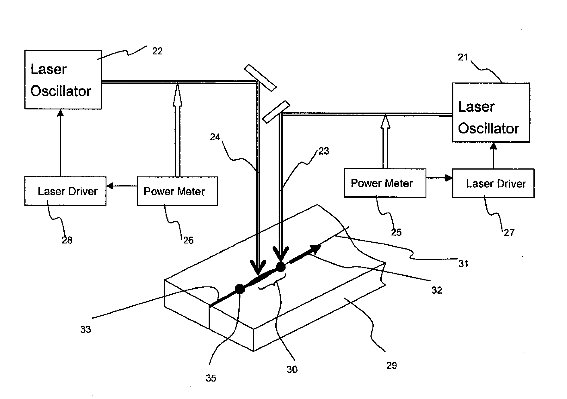
[0049]In the first exemplary embodiment of the present invention, two laser beams 23, 24 emitted from two individual laser oscillators 21, 22 are employed as the irradiating laser beam for the glass plate. CO2 laser oscillator or CO laser oscillator are used as each of the two individual oscillators, the output laser light thereof have non-transparent wavelength for the fragile materials such as glass plate. The laser beam 23 emitted from the laser oscillator 21 is appropriated as the one which heat the glass plate for initial heating and temperature rising mainly, and the laser beam 24 emitted from the laser oscillator 22 is appropriated as the one which heat the glass plate for holding temperat...

second exemplary embodiment

2. Second Exemplary Embodiment

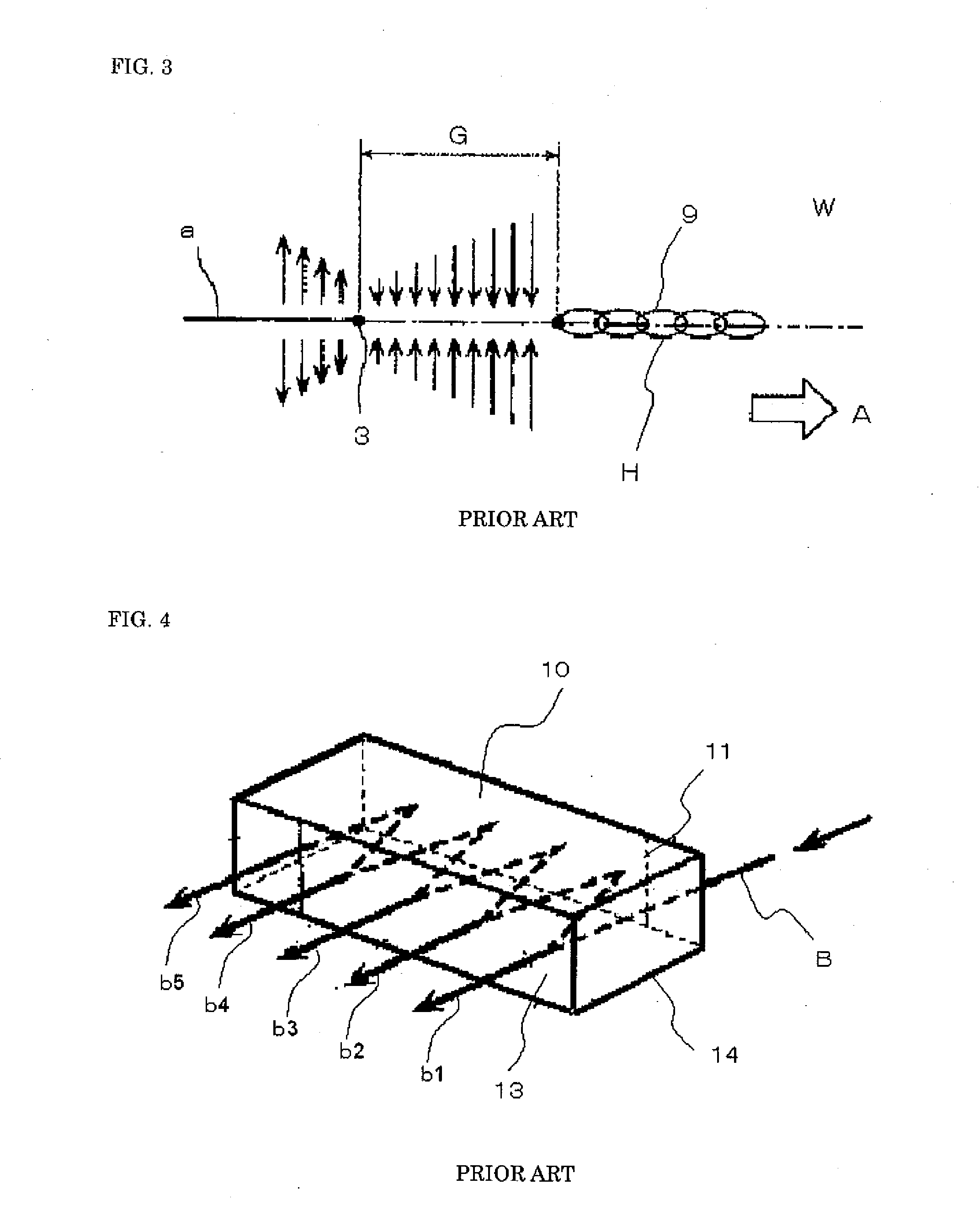
[0059]In the second exemplary embodiment of the present invention, the plurality of irradiating laser beams are formed by a beam splitter instead of using a plurality of laser oscillators. The beam splitter may be same in construction as that shown in FIG. 4, however the output beams thereof are not overlapped with each other different from that in FIG. 3.

[0060]In this embodiment, a laser beam B emitted from a laser oscillator is irradiated and transmitted into the beam splitter 14. Then, the laser beam B is split into eight outgoing laser beams b1 to b8. Three outgoing laser beams b1 to b3 are appropriated as the initial heating laser beams 19, 191 and 192 illustrated in FIG. 7A to 7C, and five laser beams b4 to b8 are appropriated as the temperature holding laser beams 20, 201 and 202 illustrated in FIG. 7A to 7C. Each of the output powers of the outgoing laser beams b1 to b3 corresponding to the initial heating laser beams is adjusted or controlled h...


PUM

PropertyMeasurementUnit
Temperatureaaaaaaaaaa
Poweraaaaaaaaaa
Stress optical coefficientaaaaaaaaaa

Abstract

In a method for scribing fragile material, a laser beam is irradiated onto a work plate of the fragile material. The work plate is heated by absorption of the irradiated laser beam and generating thermal stress by the heating. The laser beam is formed by a plurality of laser beam groups arranged along a beam scanning direction on a same line, and the plurality of laser beam groups are divided into two groups. One takes charge of initial heating and rising up temperature of the work plate, and another takes charge of temperature holding of the work plate. The laser beam intensity corresponding to each of the laser beam groups is adjusted so as to obtain optimum values.
By the method, it is possible to remarkably increase scribing speed of the work plate of the fragile materials without increasing heating temperature.

Description

FIELD OF THE INVENTION[0001]This invention relates to high speed laser scribing method of the fragile material such as fine glass used in flat panel display, quartz, ceramics or semiconductor. In order to simplify the explanation, the case of processing glass plate is represented below.BACKGROUND OF THE INVENTION[0002]The cutting of fine glass plate used in flat panel displays which are in liquid crystal (hereafter abbreviated as liquid crystal TV or plasma TV sets is presently performed using the conventional mechanical method, which is not free from the various kinds of problems such as the necessity of polishing, existence of micro-crack layer, etc. The glass used in automobile, which is mostly round-shaped, requires polishing after the mechanical straight line cutting. Tempered glass used in architecture is difficult to cut mechanically and requires a new processing method.[0003]Glass plate has been scribed so far using the mechanical method employing the ultra-hard tip such as ...

Claims


Application Information

Patent Timeline
IPC IPC(8): B23K26/00C03B33/09B23K26/38B28D5/00C03B33/033G02F1/13
CPCB23K26/0608B23K26/0676B23K26/14B23K26/1417B23K26/367H01S3/005B23K26/426B28D1/221C03B33/0222C03B33/093G02F1/133351B23K26/4075B23K26/364B23K26/705B23K26/146B23K26/40B23K2103/50C03B33/09C03B33/033B23K26/38
Inventor TAMURA, YUTAKA
Owner GLOBALY TECH CO LTD
Why Eureka
Try Eureka