Extreme ultraviolet light source apparatus and method of generating extreme ultraviolet light

Active Publication Date: 2010-04-15
GIGAPHOTON
View PDF8 Cites 62 Cited by
  • Summary
  • Abstract
  • Description
  • Claims
  • Application Information

AI Technical Summary

Benefits of technology

[0013]It is therefore an object of the present invention to resolve the above-described problems and to provide an extreme ultraviolet laser light apparatus which is able to

Problems solved by technology

However, because of using a bulk material, it is difficult to continuously form the same trenches over a long time and continuously supply the solid targets to the trenches.
Therefore, it is difficult to use the light source as a light source for the exposure apparatus that is required to drive stably over a long time.
However, in the case where the Xe target is used, because luminance efficiency of the desired EUV light with a 13.5 nm wavelength is low, the conversion efficiency becomes low (under 1%).
Therefore, it is difficult to use such apparatus using the Xe target as a light source for the exposure apparatus.
However, when the droplet being a liquid metal is irradiated with the prepulse, the dropl

Method used


Image

  • Extreme ultraviolet light source apparatus and method of generating extreme ultraviolet light
  • Extreme ultraviolet light source apparatus and method of generating extreme ultraviolet light
  • Extreme ultraviolet light source apparatus and method of generating extreme ultraviolet light

Examples


first embodiment

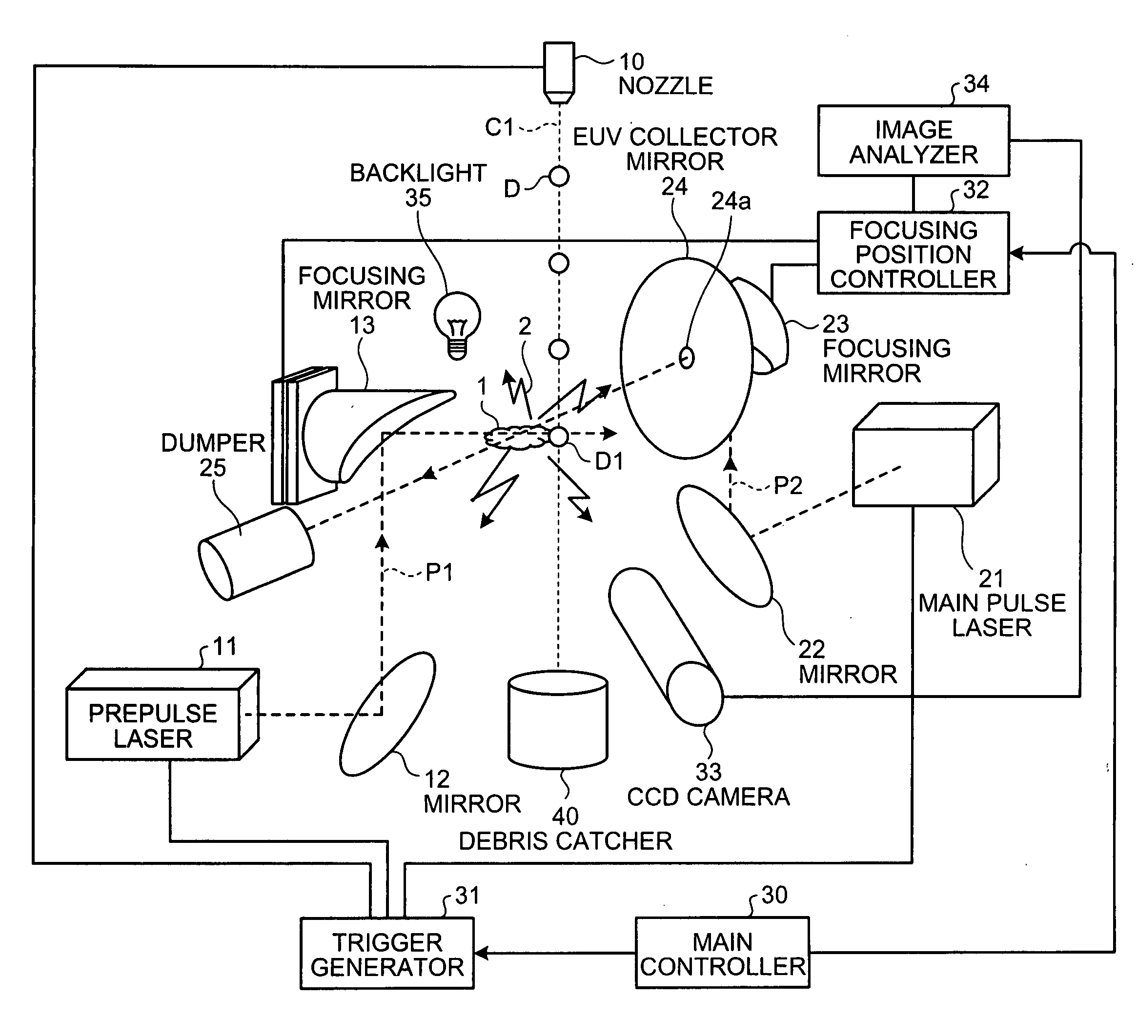
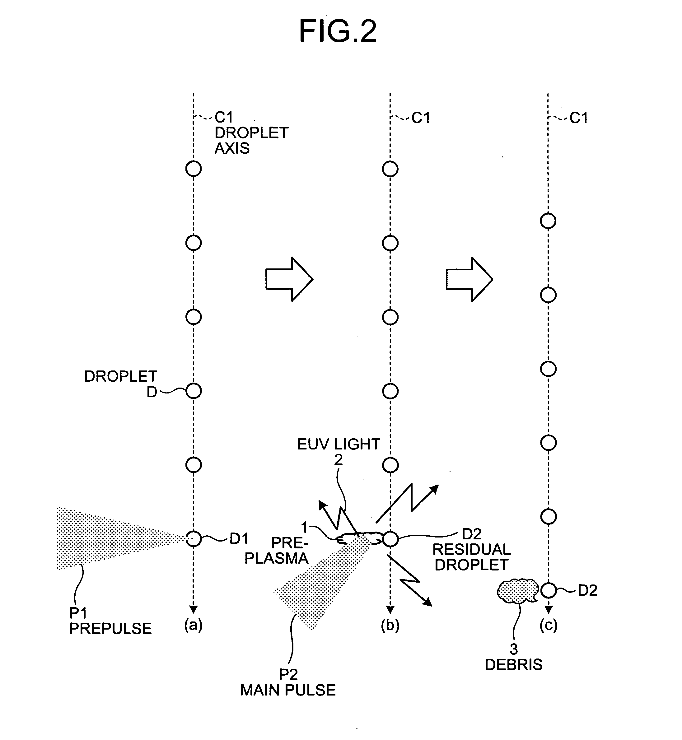
[0041]Next, an extreme ultraviolet light source apparatus according to a first embodiment of the present invention will be described in detail with reference to FIG. 4. In FIG. 4, the extreme ultraviolet light source apparatus has a nozzle 10 to discharge droplets D of Sn into a vacuum chamber (not shown), a prepulse laser 11 being a YAG laser which emits the prepulse P1 with a 1.064 μm wavelength to the droplet D1 inside the vacuum chamber at the repetition rate of 7 kHz or over, and a main pulse laser 21 being a CO2 laser which emits the main pulse laser P2 with a 10.6 μm wavelength to the pre-plasma 1 generated inside the vacuum chamber at the repetition rate of 7 kHz or over which is the same with the prepulse P1. Intensity of the prepulse P1 is equal to or greater than 1×10⁷ W / cm2 but not exceeding 1×10⁹ W / cm2. The intensity of the prepulse P1 is to the extent that enables generation of the pre-plasma 1 which is capable of emitting the desired and sufficient 13.5 nm EUV light 2...

second embodiment

[0049]In the first embodiment described above, the case where the prepulse P1 is emitted in the direction approximately perpendicular to the droplet axis C1 has been described. On the other hand, in the second embodiment, as shown in FIG. 5, the prepulse P1 is emitted in a direction approximately along the droplet axis C1.

[0050]By this arrangement, due to the debris 3 from the pre-plasma 1 being generated along the droplet axis C1 after the pre-plasma 1 is irradiated with the main pulse P2, the debris catcher 40 can easily retrieve not only the residual droplet D2 but also the debris 3 generated from the pre-plasma 1. In this case, an aperture of the debris catcher 40 can be designed based on how the debris 3 expand from the droplet axis C1. Accordingly, it is possible to keep an amount of the flying debris 3 to a minimum. In addition, as shown in FIG. 5, due to the EUV collector mirror 24 being mounted in the direction perpendicular to a flying direction of the debris 3, i.e. the m...

third embodiment

Alternate Example 5 of Third Embodiment

[0083]In this alternate example 5, a dimple target 150 having dimples is used as a solid target. As shown in FIG. 15, the dimple target 150 is the same as the tape target 130 shown in FIG. 13, expect that the dimples 153 are formed on a front surface of the dimple target 150. That is, in the dimple target 150, the dimples 153 formed on one wide front face of a tape-type core portion 151 are coated with the target materials 152. The dimples 153 are arrayed along a direction of a target axis C60. Although the dimples 153 are formed on the tape-type target material 152, it is possible to form the dimples 153 by having dimples provided on a surface of the core portion 151 while the target material 152 is to be formed and having the core portion 151 including the dimples coated with the target material 152.

[0084]When the target material 153 is irradiated with the prepulse P1 from an approximately perpendicular direction to a face of the target mater...


PUM


Abstract

An extreme ultraviolet light source apparatus, which is to generate an extreme ultraviolet light by irradiating a target with a main pulse laser light after irradiating the target with a prepulse laser light, the extreme ultraviolet light source apparatus comprises: a prepulse laser light source generating a pre-plasma by irradiating the target with the prepulse laser light while a part of the target remains, the pre-plasma being generated at a different region from a target region, the different region being located on an incident side of the prepulse laser light; and a main pulse laser light source generating the extreme ultraviolet light by irradiating the pre-plasma with the main pulse laser light.

Description

CROSS-REFERENCE TO RELATED APPLICATIONS[0001]This application is based upon and claims the benefit of priority from the prior Japanese Patent Applications No. 2008-250744, filed on Sep. 29, 2008, and No. 2009-212884, filed on Sep. 15, 2009; the entire contents of which are incorporated herein by reference.BACKGROUND OF THE INVENTION[0002]1. Field of the Invention[0003]The present invention relates to an extreme ultraviolet light source apparatus generating an extreme ultraviolet light by irradiating a liquid metal target with a main pulse laser light after irradiating the target with a prepulse laser light, and a method of generating an extreme ultraviolet light.[0004]2. Description of the Related Art[0005]In recent years, along with a progress in miniaturization of semiconductor device, miniaturization of transcription pattern used in photolithography in a semiconductor process has developed rapidly. In the next generation, microfabrication to the extent of 70 nm to 45 nm, or even ...

Claims


Application Information

Patent Timeline
IPC IPC(8): G21K5/00
CPCG03F7/70033H05G2/003H05G2/00G21K5/00H05G2/008
Inventor ENDO, AKIRAUENO, YOSHIFUMISASAKI, YOUICHIWAKABAYASHI, OSAMU
Owner GIGAPHOTON
Why Eureka
Try Eureka