
Pitch of Blades on a Wind Power Plant

a technology of wind power plants and blades, which is applied in the direction of propellers, engine control parameters, water-acting propulsive elements, etc., can solve the problems of reducing the rotor area, undesirable reduction in the power yield, and the deformation of the blades is often a limiting dimensioning factor, so as to achieve the effect of optimizing the rotor area

Active Publication Date: 2010-04-15
LM GLASSFIBER
View PDF6 Cites 21 Cited by
  • Summary
  • Abstract
  • Description
  • Claims
  • Application Information

AI Technical Summary

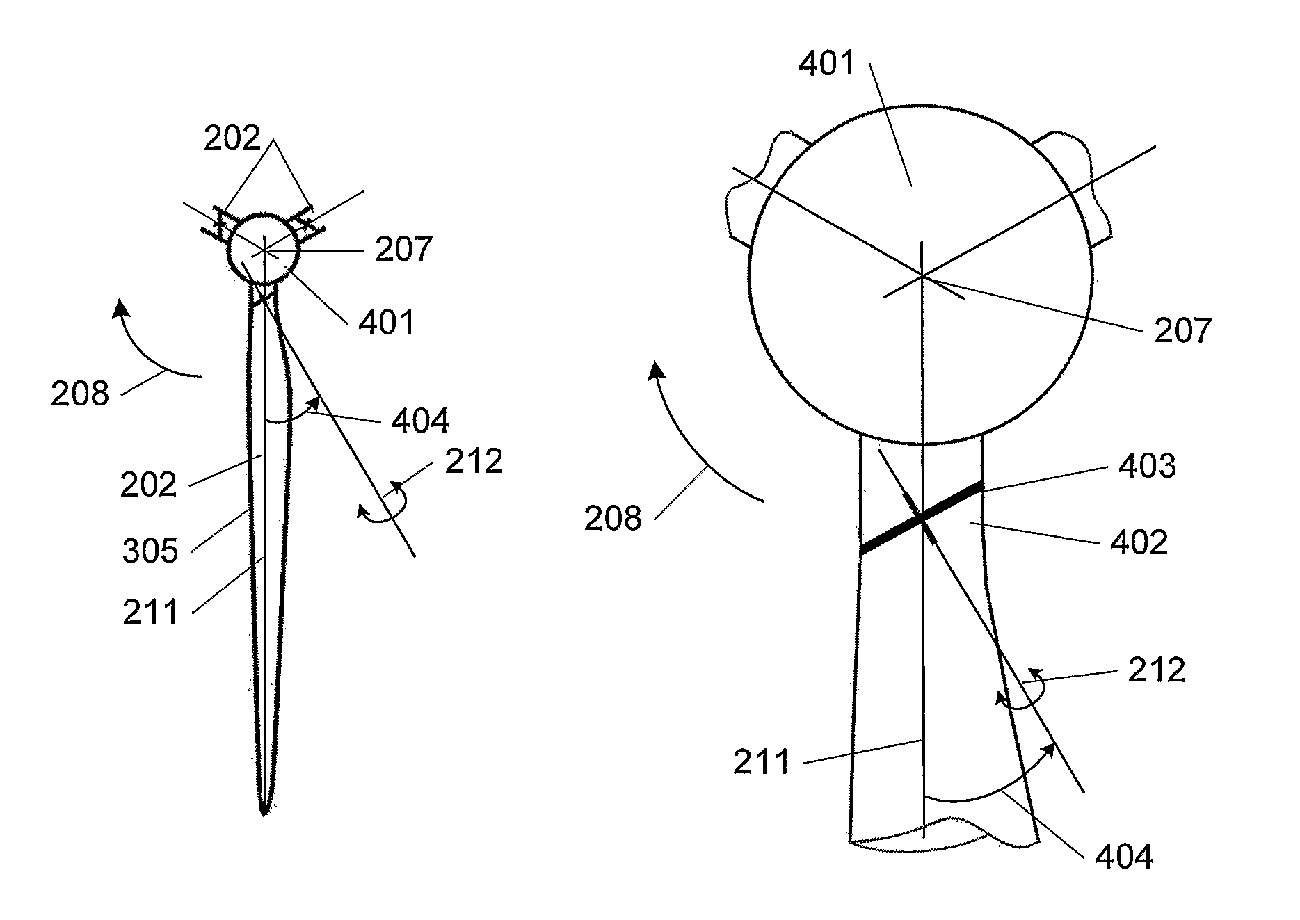
Benefits of technology

[0011]It is the object of the invention to provide a wind power plant to obviate the above-mentioned problems of reducing the effective rotor area and clearance between blade and tower.
[0012]The present invention thus relates to a blade for a wind power plant, which blade comprises at least one assembly face for mounting in a circular pitch bearing with a pitch axis angled relative to the longitudinal axis of the blade. The blade comprises a root part with an approximately elliptic cross-section approximately perpendicular to the longitudinal axis of the blade, in which root part the at least one assembly face is arranged. An embodiment of the invention additionally relates to a blade further comprising at least one pitch bearing. The pitch axis being angled relative to the longitudinal axis of the blade, the advantageous aspect is accomplished that a blade mounted on a wind power plant can be moved into and out of the rotor plane when pitched. For instance, this enables control and regulation of the clearance between blade and tower during tower passage by pitching of the blade, and, likewise, the rotor area can be optimized by pitching. More and other advantages will appear from the below. The elliptical cross-section of the root part of the blade is advantageous in that a blade is accomplished that has an approximately smooth, uninterrupted and continuous transition across the pitch bearing, albeit turned compared to its usual position where it sits perpendicular to the longitudinal axis of the blade. Moreover, a very simple construction may provide a blade that can be pitched about other axes than that of the blade—merely by a simple adaptation of the shape of the blade root.
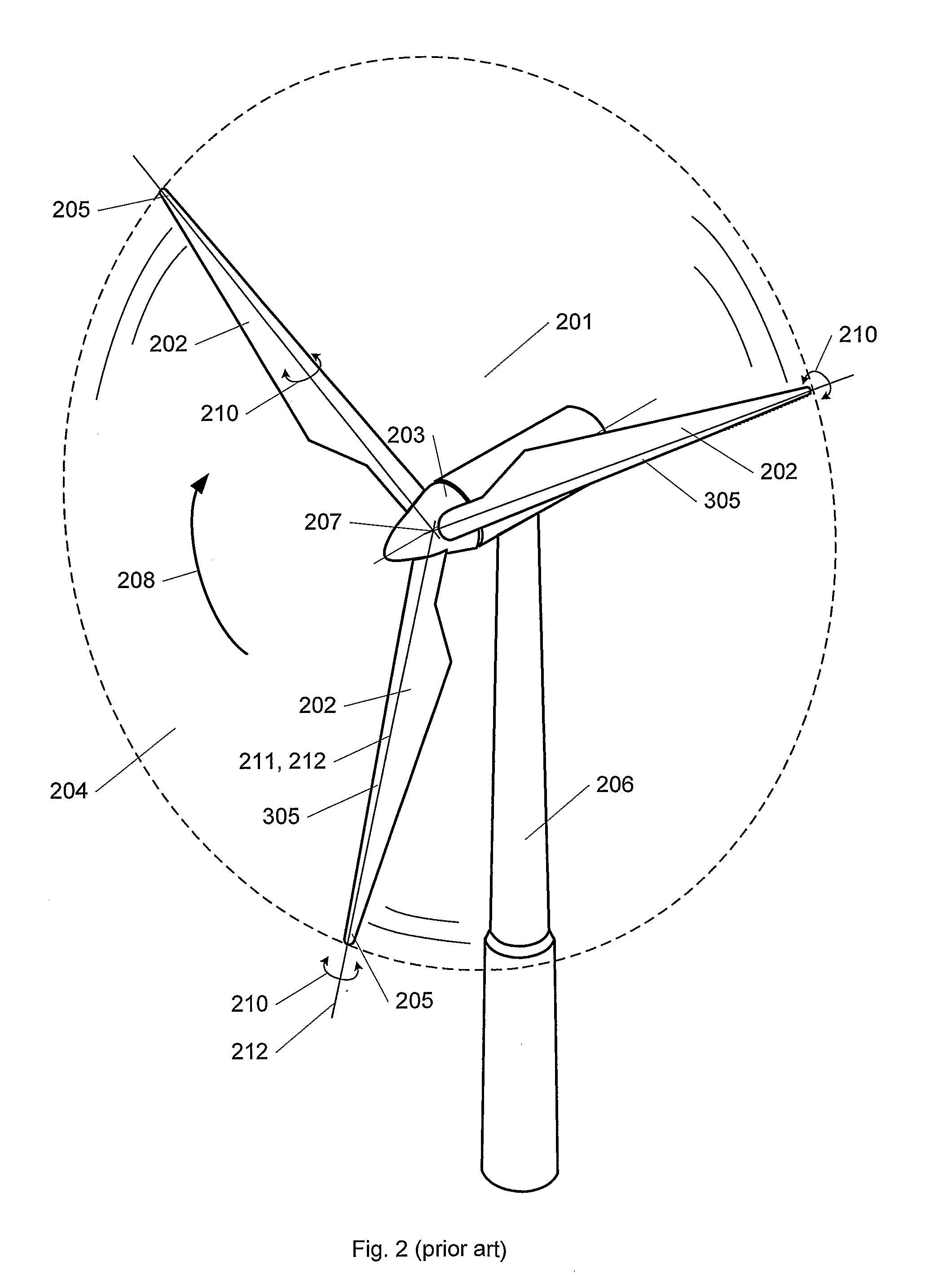
[0013]The present invention also relates to a wind power plant comprising a tower and a rotor with a number of blades of which at least one pitch-adjustable blade is mounted turnably in a pitch bearing, and wherein the longitudinal axis of at least one blade is angled relative to its pitch axis, whereby the distance between the outermost part of the blade and the tower is increased when the leading edge of the blade is pitched upwards in the wind. Hereby the advantageous aspect is accomplished that it is possible to move the entire or a part of each blade in a more complex and advanced manner than conventional pitch-adjusted turbines, where, by pitching, the blades can be turned about their longitudinal axis only. Hereby improved control of the wind power plant as a function of wind velocities and rotation rates is enabled.

Problems solved by technology

It follows that the deformation of the blades lead to a reduction in the rotor area and hence to an undesirable reduction in the power yield.
Moreover, the deformation of the blades is often a limiting dimensioning factor to the design of new wind power plants, as one has to make sure that the blades do not hit the tower.
Positioning of the rotor a further distance from the tower is not desirable, an increased length of the main shaft giving rise to a larger momentum on the tower and hence to undesirable forces in is gears and bearings in the hub.
However, the complete useful length of the blade is still achieved only at precisely the specific design wind velocity.
However, both of these construction methods entail a reduction in the effective rotor area compared to blades of a specific length and hence a reduction in the achievable power yield.
The blade is constructed such that turbulence is generated on the rear side when it is very windy.

Method used


Image

  • Pitch of Blades on a Wind Power Plant
  • Pitch of Blades on a Wind Power Plant
  • Pitch of Blades on a Wind Power Plant

Examples


Embodiment Construction

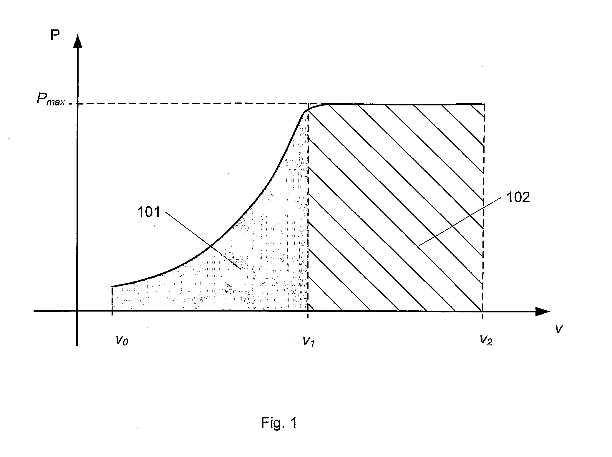
[0037]FIG. 1 schematically shows a typical output curve for a wind power plant. The curve shows the achieved power P as a function of the wind velocity v. The wind power plant starts to produce current at a starting wind with velocity v0, where, in case of pitch-adjusted and actively stall-adjusted pitches, it often takes a pitch of 5° to start the rotor. Here and in the following, a positive pitch angle is defined by the leading edge of the blade profile being turned up into the wind, as also outlined more detailed in the following FIG. 3. From here, the power output increases with increasing wind velocities, until the velocity v1. Within this range 101, the wind power plant is constructed to maximize the power yield and productivity of the wind power plant. At the wind velocity v1, the wind power plant yields the maximum power Pmax. The magnitude of the velocity v1 depends on different factors, such as financial factors, including eg the size of the generator and local wind condit...


PUM


Abstract

The present invention relates to a blade for a wind power plant with an assembly face for mounting in a circular pitch bearing, whose pitch axis is angled relative to the longitudinal axis of the blade, and wherein the blade comprises a root part with an approximately elliptic cross-section, in which root part the assembly face is arranged. The invention further relates to a wind power plant in general having a pitch-adjustable blade mounted in a pitch bearing such that the distance between the outermost part of the blade and the tower is increased when the leading edge of the blade is pitched up in the wind. This is accomplished in that the longitudinal axis of the blade is angled in a particular way compared to its pitch axis. The invention also relates to a meth controlling a wind power plant, including to increase the rotor area and / or increasing the distance between the outermost part of at least one blade and the tower by regulating, during operation, the pitch of a blade about a pitch axis which is angled relative to the longitudinal axis of the blade.

Description

[0001]The invention relates to a blade for a wind power plant and a wind power plant comprising a tower and a rotor with a number of blades, of which at least one blade is mounted to be pitch-adjustable in a pitch bearing. Moreover, the invention relates to methods of controlling such wind power plant.BACKGROUND[0002]The achievable electricity output of a wind power plant depends directly on the size of the rotor area and hence on the effective length of the blades. A blade which is 1% shorter will thus result, as a rule of thumb, in a 2-3% lower electricity output. As a result of efforts to save material and weight, the blades of a wind power plant are often very flexible, and the flexing due to the wind may thus be quite comprehensive. It follows that the deformation of the blades lead to a reduction in the rotor area and hence to an undesirable reduction in the power yield.[0003]Moreover, the deformation of the blades is often a limiting dimensioning factor to the design of new w...

Claims


Application Information

Patent Timeline
IPC IPC(8): F03D7/04F03D1/06
CPCF03D1/0658F03D7/0224F03D7/0236F03D7/0288F03D7/042F05B2250/14Y02E10/723F05B2260/70F05B2260/74F05B2270/17F05B2270/33Y02E10/721F05B2250/314Y02E10/72F03D80/00F03D7/022F03D7/0244
Inventor SORENSEN, TOMMY
Owner LM GLASSFIBER
Learn More