
Fuel cell assembly structure

a technology of assembly structure and fuel cell, which is applied in the direction of fuel cells, cell components, electrical equipment, etc., can solve the problems of fragile structure, limited electrical energy produced by single cell modules, and rarely useful, and achieve the effect of reducing production costs, simple structure and geometrical shap

Inactive Publication Date: 2010-04-22
INST NUCLEAR ENERGY RES ROCAEC
View PDF3 Cites 0 Cited by
  • Summary
  • Abstract
  • Description
  • Claims
  • Application Information

AI Technical Summary

Benefits of technology

[0007]The main objective for the invention is to provide an assembly structure for fuel cell with simple structure and geometrical shape for components. It is not only easy for assembly but also very competitive because its production cost is reduced.
[0008]Another objective for the invention is to provide an assembly structure for fuel cell with modulized structure, so it allows easy replacement of the only damaged component to lower usage cost and it also enables capacity expansion to increase application range.
[0009]Another objective for the invention is to provide an assembly structure for fuel cell that is easy to take apart and provides convenience during repair.

Problems solved by technology

But because a single cell module produces a very limited amount of electrical energy (voltage, current).
However, such a structure is fragile, rarely useful, and hard to repair interiors and lower maintenance cost.
However, such structure (a plurality of holes around anode and cathode) lacks design for restriction and positioning at edge, so the accommodating space inside the housing lacks the shape that fits.
As a result, since the connection and positioning between cell modules is not easy, it increases the difficulty in assembly.
Besides, the single module product that lacks integration is hard to disassemble and replace components and therefore the cost for maintenance, repair and usage too high to be competitive and to offer economic benefits.

Method used


Image

  • Fuel cell assembly structure
  • Fuel cell assembly structure
  • Fuel cell assembly structure

Examples


Embodiment Construction

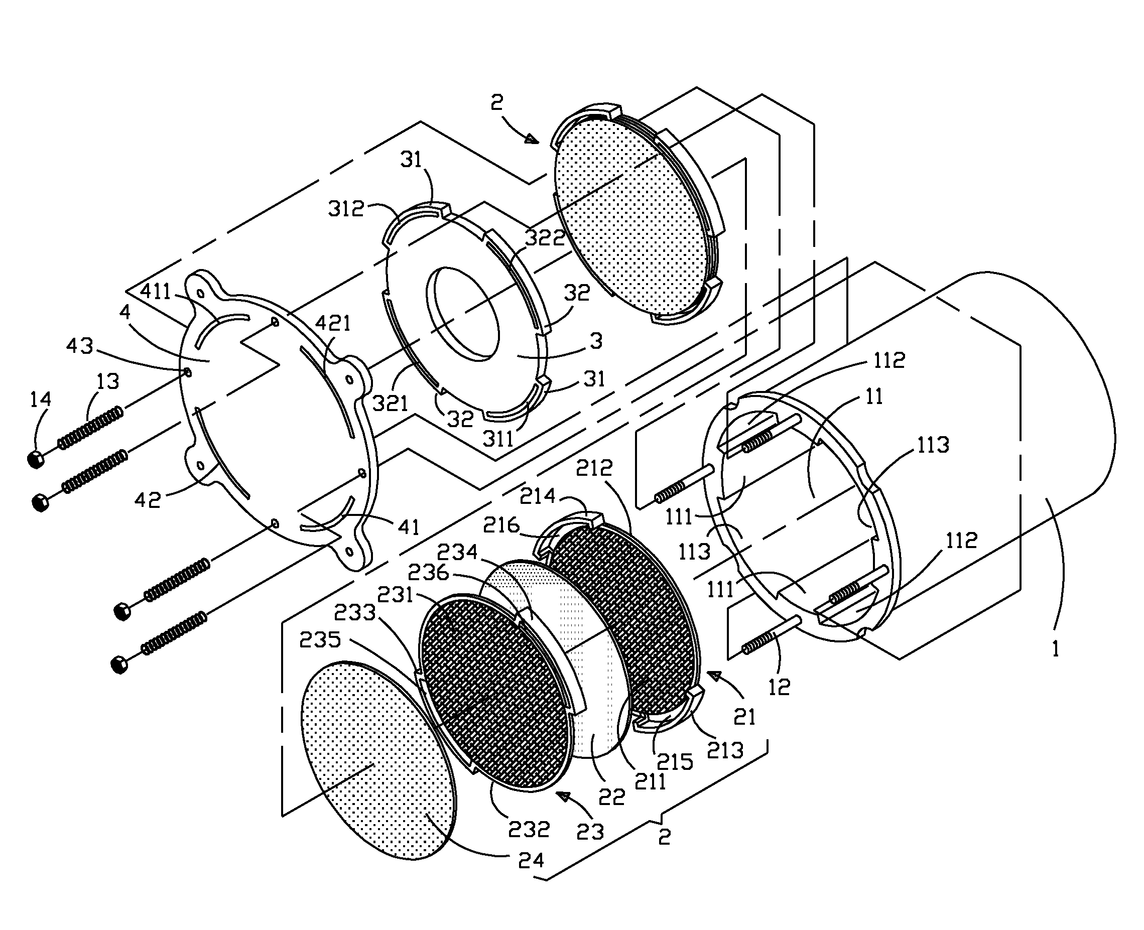
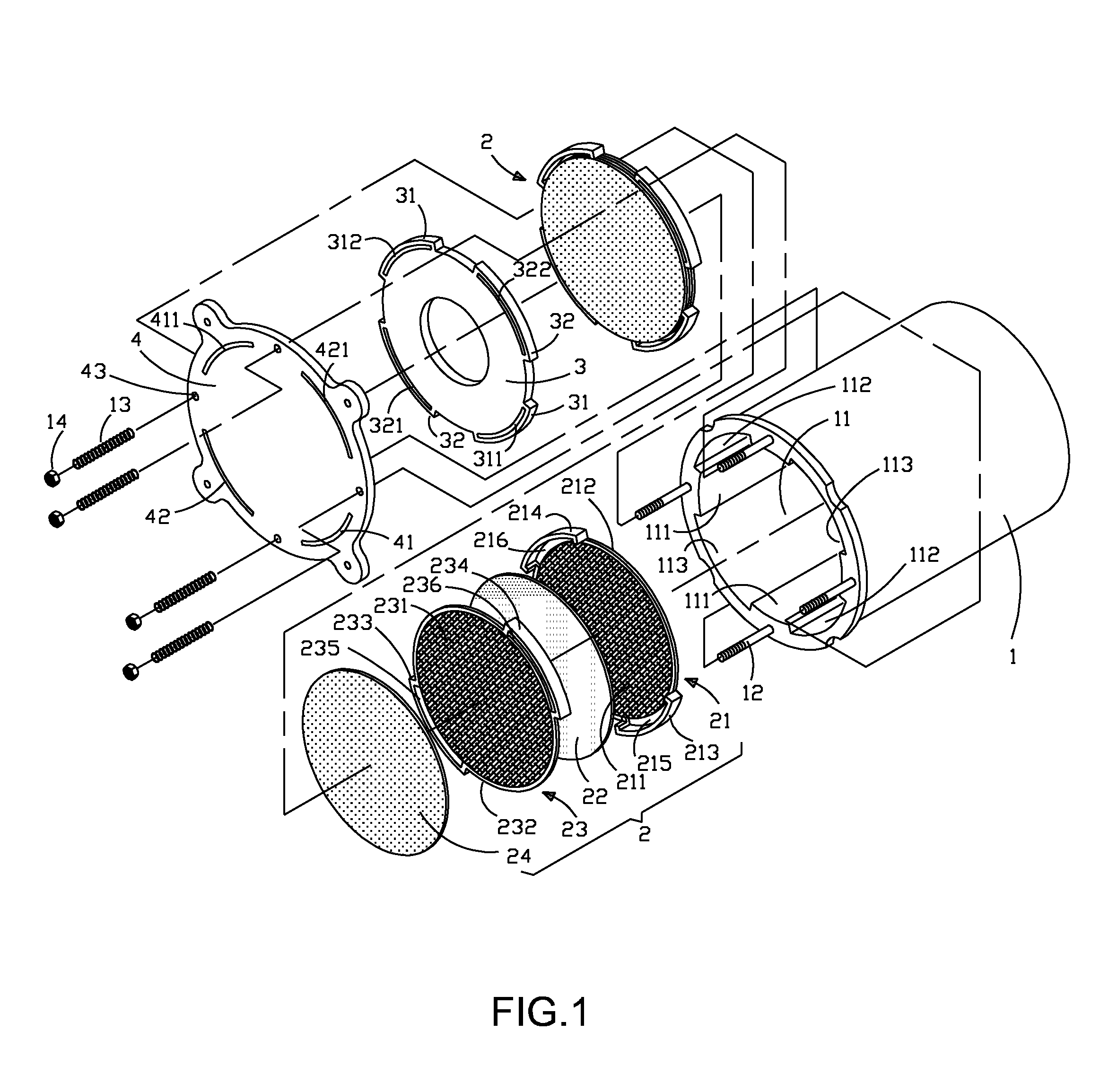
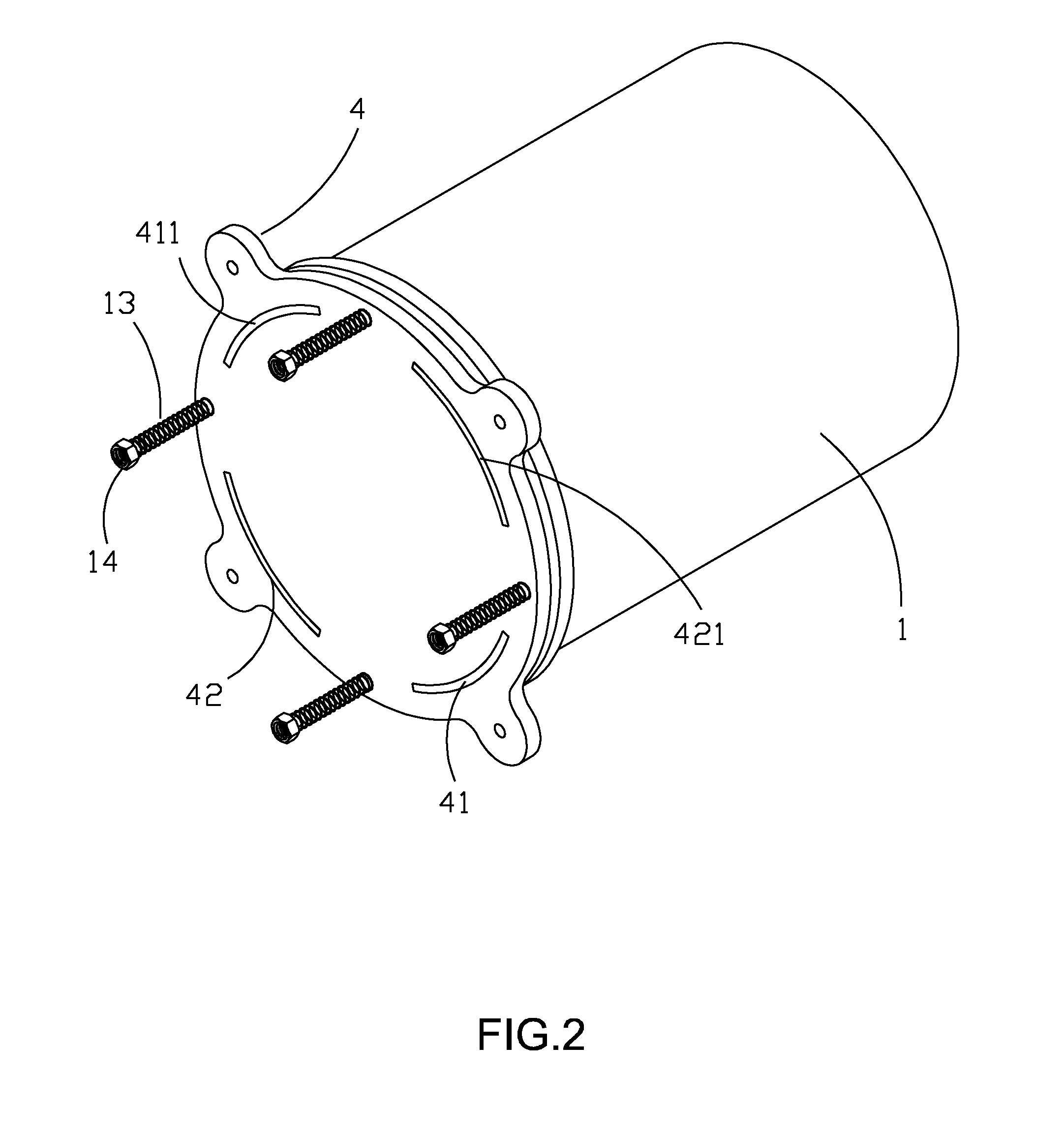
[0020]Please refer to the figures. It can be clearly found that the invention mainly comprises a housing 1, unit cell stack 2, sealing disk 3 and cover 4 etc. In the housing 1 there is a surface coating of insulation (ceramic) material for the accommodating space 11. On the inner periphery of the accommodating space 11 there are at least two sets (at least four lines) of symmetric and extending convex ribs 111 along the central axis, so between the convex ribs 111 there form two sets of symmetric concaves 112, 113. Besides, around the opening of the accommodating space 11, there is a plurality of bolts 12. A unit cell stack 2 is made by stacking a cathode layer 21, a power generation electrode 22, an anode layer 23 and a connection disk 24 in sequence. The cathode layer 21 is a cathode grid 211 (antioxidative metals or ceramic oxides) that has a press-sealing ring 212 around its periphery. Around the outer periphery of the press-sealing ring 212 there are two sets of symmetric first...


PUM

PropertyMeasurementUnit
chemical energyaaaaaaaaaa
electrical energyaaaaaaaaaa
timeaaaaaaaaaa

Abstract

A fuel cell assembly structure mainly comprises a housing in which there is an accommodating space; a plurality of unit cell stacks that are stacked in the same direction in the accommodating space of the housing and made by stacking in sequence a cathode layer, a power generation electrode, an anode layer and a connection disk; a connection disk connecting is series each unit cell stack, a sealing disk and a cover in sequence to cover the opening of the accommodating space of the housing. On the outer side of the cover there is a connection base, at least one surface of which has a plurality of conduits and the other end connects to a plurality of cell stack bypass manifolds that further connect to a plurality of side bypass manifolds.

Description

BACKGROUND OF THE INVENTION [0001]1. Field of the Invention[0002]The invention relates to a fuel cell assembly structure, which especially refers to a simple structure that can be easily produced and dissembled with reduced production cost and increased product competitiveness.[0003]2. Description of the Prior Art[0004]Fuel cell is a device that uses fuel (hydrogen, oxygen as most common) to conduct chemical reaction and directly converts chemical energy into electrical energy. Since it has high conversion efficiency, wide range of fuel selection, no hazard in reaction process and useable by-product (water), it is generally considered as an alternative energy to fossil fuel.[0005]In the principle of solid oxide fuel cell, the oxygen atom at cathode receives electrons by means of catalytic effect to turn into oxygen ion in reduction reaction. The oxygen ion is transported through electrolyte to anode and reacts with the fuel to produce water. At anode, oxidation reaction occurs and e...

Claims


Application Information

Patent Timeline
Patent Type & Authority Applications(United States)
IPC IPC(8): H01M2/08H01M2/18
CPCH01M8/2475Y02E60/50H01M8/249H01M8/2485H01M8/0273H01M8/2484
Inventor YU, DUNG-DICHENG, YUNG-NENGLEE, RUEY-YILEE, CHIEN-HSIUNG
Owner INST NUCLEAR ENERGY RES ROCAEC
Learn More