Powerplant and related control system and method

a control system and power plant technology, applied in the ignition of turbine/propulsion engines, special data processing applications, gaseous engine fuels, etc., can solve the problems of limiting the payload (or duration) of the aircraft, wasting energy of compression for that unburned portion of the air, and reducing reliability, so as to achieve rapid change of operating levels and reduce the effect of power consumption

a control system and power plant technology, applied in the ignition of turbine/propulsion engines, special data processing applications, gaseous engine fuels, etc., can solve the problems of limiting the payload (or duration) of the aircraft, wasting energy of compression for that unburned portion of the air, and reducing reliability, so as to achieve rapid change of operating levels and reduce the effect of power consumption

US20100100300A1Active Publication Date: 2010-04-22AEROVIRONMENT INC

Image

  • Powerplant and related control system and method
  • Powerplant and related control system and method
  • Powerplant and related control system and method

Examples


Embodiment Construction

[0020]The invention summarized above and defined by the enumerated claims may be better understood by referring to the following detailed description, which should be read with the accompanying drawings. This detailed description of particular preferred embodiments of the invention, set out below to enable one to build and use particular implementations of the invention, is not intended to limit the enumerated claims, but rather, it is intended to provide particular examples of them.

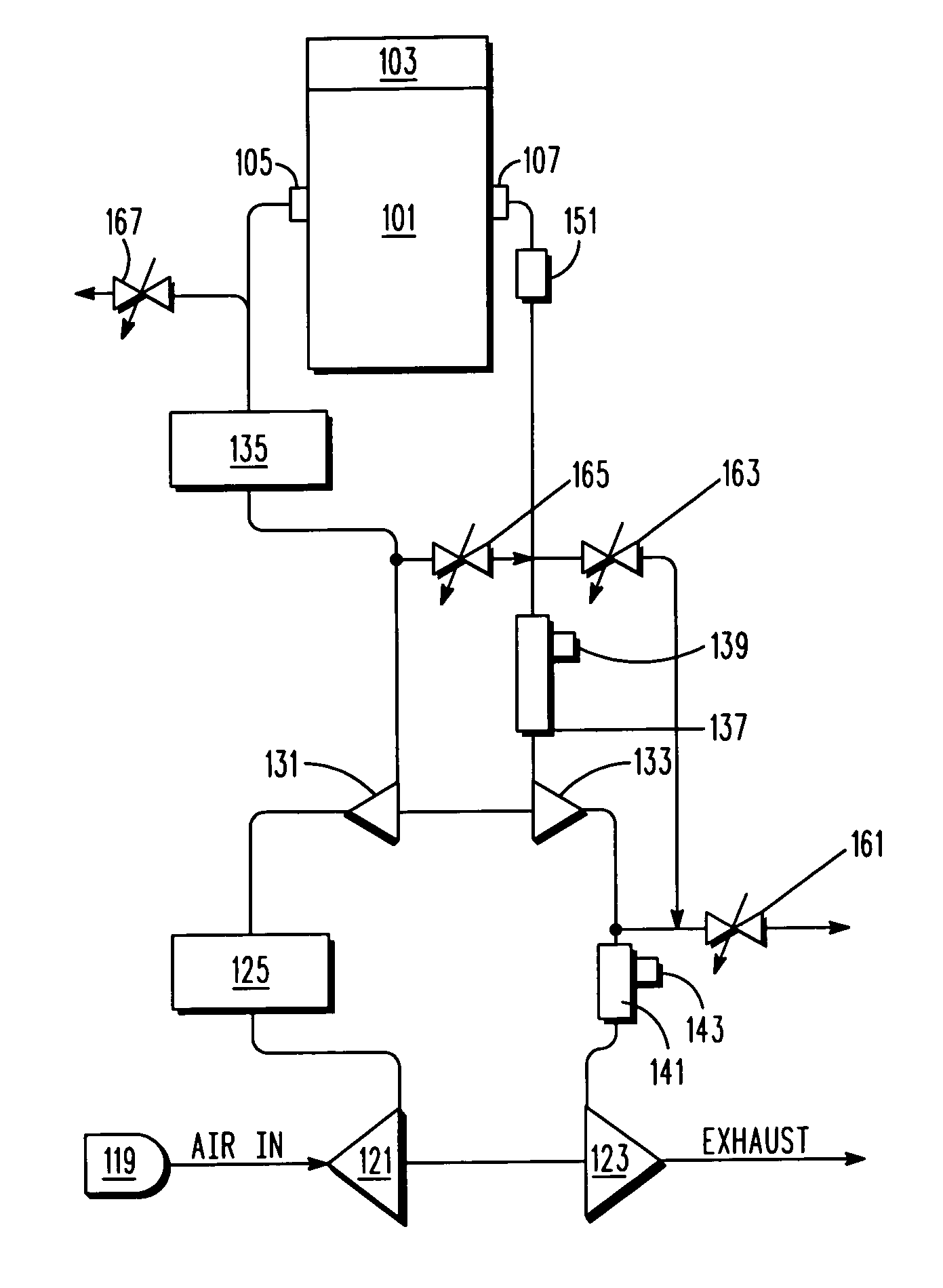
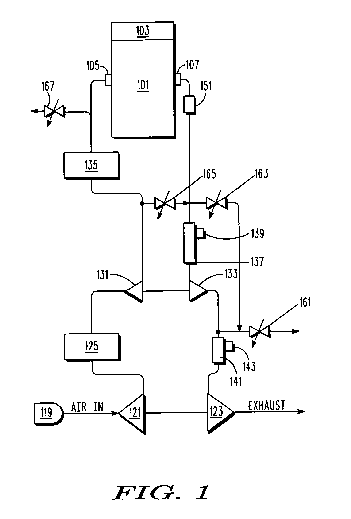
[0021]Typical embodiments of the present invention reside in a powerplant for a high-altitude long-endurance aircraft. The powerplant includes an engine (i.e., a machine that converts energy into mechanical force or motion) and a primary motor-generator configured to generate electricity using the motive force of the engine, to provide motive force to spin the engine, and to provide motive force to the engine to regulate the speed with which the engine spins. The engine uses a first reactant and a gaseou...


PUM


Abstract

A hydrogen fueled powerplant including an internal combustion engine that drives a motor-generator, and has a two-stage turbocharger, for an aircraft. A control system controls the operation of the motor-generator to maintain the engine at a speed selected based on controlling the engine equivalence ratio. The control system controls an afterburner, an intercooler and an aftercooler to maximize powerplant efficiency. The afterburner also adds power to the turbochargers during high-altitude restarts. The turbochargers also include motor-generators that extract excess power from the exhaust.

Description

[0001]This application claims the benefit of U.S. provisional Application No. 61 / 194,048, filed Sep. 23, 2008, which is incorporated herein by reference for all purposes.[0002]The present invention relates generally to a hydrogen powerplant and, more particularly, to a powerplant having a hydrogen combustion engine, a turbocharger and an afterburner.BACKGROUND OF THE INVENTION[0003]High altitude long endurance aircraft require extremely efficient designs. Hydrogen-powered aircraft have been previously suggested to limit fuel weight and thereby maximize endurance. Regardless of the selected fuel, an oxidizer must be provided, and if ambient air is to be the oxidizer, it typically must be compressed at high altitudes. When hydrogen is the fuel, a significant amount of compressed air may remain unburned by an engine, and thus the energy of compression may be wasted for that unburned portion of the air.[0004]It has been suggested that the use of electric motors for propulsion may be ben...

Claims


Application Information

Patent Timeline
22 Apr 2010
Publication
US20100100300A1
IPC
F02D43/00; F02D23/00; F01N3/10; F02B43/00; F01N9/00; F02N11/04; H02P9/04
CPC
B60W2710/0644; F02C7/26; F02B37/013; F02B37/18; F02B37/20; F02D29/06; F02D41/0007; F02D41/0025
Inventors
BROOKS, ALEXANDER NELSON; DALEY, JAMES GALLAGHER