Evaporative Cooler and Use Thereof and Gas Turbine System Featuring an Evaporative Cooler

a technology of evaporative cooler and gas turbine system, which is applied in the direction of machines/engines, liquid/solution decomposition chemical coating, light and heating apparatus, etc., can solve the problems of limited erosion danger of system components connected downstream on the flow medium side, especially the compressor blades, and achieve improved wettability and good cooling effects , the effect of high efficiency of the intake cooler

Inactive Publication Date: 2010-04-29
SIEMENS AG
View PDF10 Cites 12 Cited by
  • Summary
  • Abstract
  • Description
  • Claims
  • Application Information

AI Technical Summary

Benefits of technology

[0031]The particular advantage of the invention is that, as a result of the selective surface treatment and hydrophilization of the modules and cooling elements (in particular of honeycombed cooling sheets) which are provided for liquid vaporization or evaporation in an evaporative cooler, an enlargement or more efficient utilization of the active heat transfer surface is achieved by virtue of the improved wettability. When such an evaporative cooler is used to cool a gas stream, e.g. in an intake cooler of a gas turbine, particularly good cooling effects can be achieved, even when using a comparatively modest supply of liquid. At the same time, any sweeping up of liquid drops by the gas flow is largely suppressed or prevented, thereby reducing the danger of e.g. corrosion and erosion for a thermal reciprocating engine or a thermal fluid-flow machine, in particular a gas turbine, which is arranged behind the evaporative cooler. As a result of the high efficiency of the intake cooler, the efficiency and the power yield of the subsequent gas turbine also increases.
[0032]A further advantage of the concept proposed here is that, as a result of the improved surface utilization, the installation depth of the evaporative cooler can be smaller than previously for the same cooling power. As a result of the reduced structural depth, it is possible to achieve a more compact design of the housing and hence a reduction in manufacturing costs. Moreover, less pressure loss is experienced in the intake section than was previously the case.
[0033]The concept of hydrophilization of vaporization or evaporation surfaces can also be advantageously applied to increase efficiency in the case of falling-film vaporizers, whose primary purpose is not the cooling of a gas stream but the production of vapor itself, e.g. in the process engineering for the distillation of liquid mixtures, etc. Instead of or in addition to heating by means of a hot gas stream, e.g. electrical heating of downflow sheets or tubes can also be provided in this case.

Problems solved by technology

In particular, when using such an evaporative cooler as an intake cooler for a gas turbine, the erosion danger for the system components that are connected downstream on the flow medium side, especially the compressor blades, is limited.

Method used


Image

  • Evaporative Cooler and Use Thereof and Gas Turbine System Featuring an Evaporative Cooler
  • Evaporative Cooler and Use Thereof and Gas Turbine System Featuring an Evaporative Cooler

Examples


Embodiment Construction

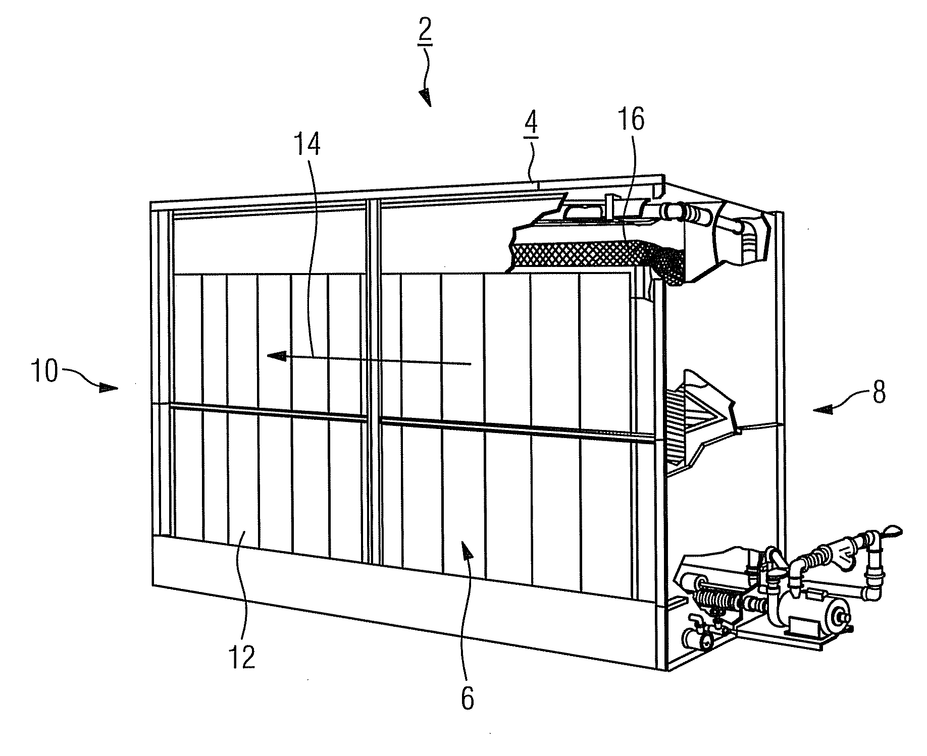
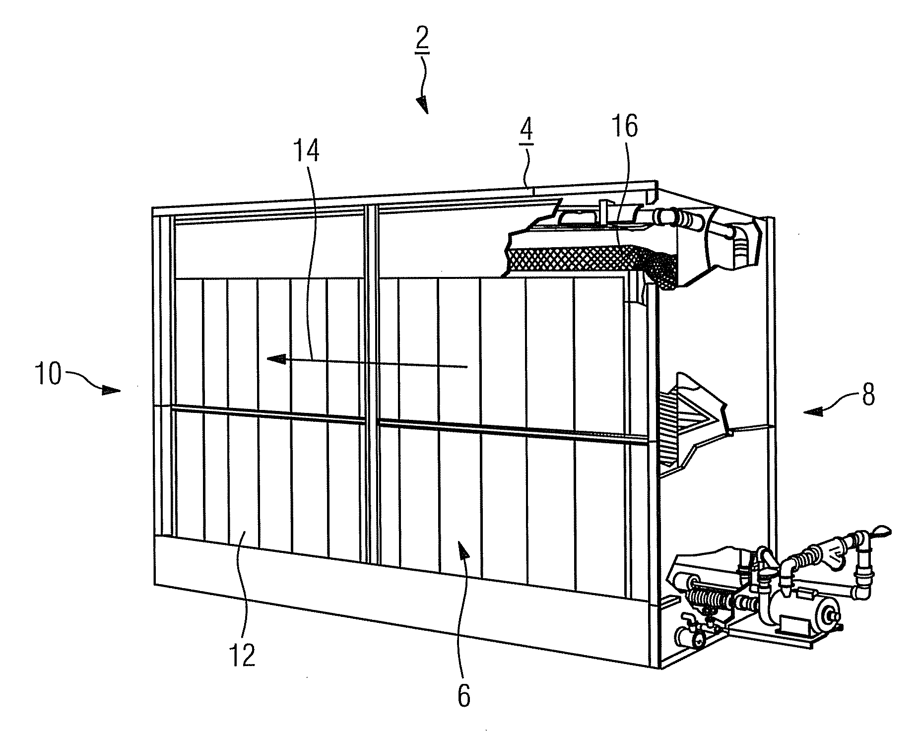
[0035]The evaporative cooler 2 which is illustrated in the figure is used as an intake cooler for the purpose of cooling intake air that is drawn in from the environment and is supplied to a compressor of a gas turbine (not shown). For this, it features a flow channel 6, this being surrounded by a closed housing 4 and comprising an air inlet 8 and an air outlet 10, in which is arranged a plurality of cooling elements 12 or cooling sheets, these being combined into groups or cooling modules in each case. The flat cooling elements 12 are in each case oriented vertically and parallel to the flow direction 14 of the air flow that forms during operation, and can be supplied with water on both sides via a feed device 16 which is arranged in the cover region of the housing 4 or on the top side of the relevant cooling element 12. A water film running from top to bottom therefore forms on both the “front side” and on the “rear side” of the relevant cooling element 12 during operation, and th...


PUM

PropertyMeasurementUnit
contact angleaaaaaaaaaa
temperatureaaaaaaaaaa

Abstract

An evaporative cooler for cooling a gas stream, in particular an air stream, including a number of cooling elements located in a flow channel, is provided. A liquid, preferably water, is supplied by a feed device and will be vaporized or evaporated. In one aspect, the surface of at least one of the cooling elements has hydrophilic properties, at least in one sub-region designed to form a liquid film.

Description

CROSS REFERENCE TO RELATED APPLICATIONS[0001]This application is the US National Stage of International Application No. PCT / EP2008 / 051127, filed Jan. 30, 2008 and claims the benefit thereof. The International Application claims the benefits of European Patent Office application No. 07002345.2 EP filed Feb. 2, 2007, both of the applications are incorporated by reference herein in their entirety.FIELD OF INVENTION[0002]The invention relates to an evaporative cooler for cooling a gas stream, in particular an air stream, comprising a number of cooling elements which are arranged in a flow channel and, by means of a feed device, can be supplied with a liquid (preferably water) that is to be evaporated or vaporized. The invention also relates to a use of such an evaporative cooler and to a gas turbine system featuring an evaporative cooler.BACKGROUND OF INVENTION[0003]The efficiency of the energy conversion in a gas turbine, and in particular its power output, depend inter alia on the int...

Claims


Application Information

Patent Timeline
Patent Type & Authority Applications(United States)
IPC IPC(8): F02C7/14F25B39/02
CPCC09D1/00C23C18/1254C25D11/02F01D25/305F02C7/143F28C3/08F28F13/18F28F2245/02F02C7/1435F28C1/02
Inventor BIRKNER, JENSDAVID, WALTERGENSLER, RUDOLFGRASSMANN, ARNEHALBERSTADT, KNUTHEIMBERG, BEATEKOCDEMIR, BORANIES, RAINERSCHURHOFF, JORGSTAMM, WERNER
Owner SIEMENS AG
Why Eureka
Try Eureka