
Laser Machining Medical Devices With Localized Cooling

a technology of local cooling and laser machining, which is applied in the direction of manufacturing tools, prosthesis, welding/soldering/cutting articles, etc., can solve the problems of adverse effects of laser machining on adverse effects of laser machining on the mechanical and other properties in the heat affected zone, etc., to reduce or prevent heat transfer

Inactive Publication Date: 2010-04-29
ABBOTT CARDIOVASCULAR
View PDF17 Cites 35 Cited by
  • Summary
  • Abstract
  • Description
  • Claims
  • Application Information

AI Technical Summary

Benefits of technology

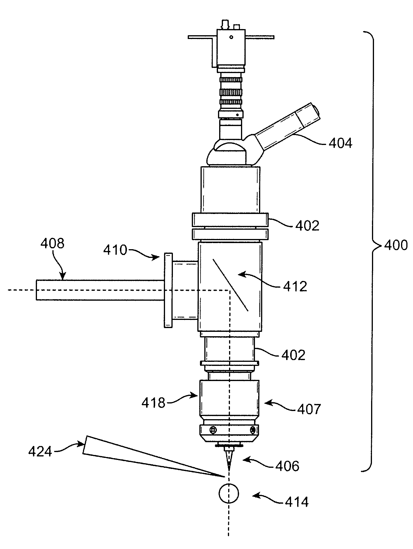
[0016]Various embodiments of the present invention includes a method of fabricating a stent, comprising: directing a pulsed laser beam through a focusing head of a laser machining apparatus to a surface of a tubular construct comprising a polymer layer, wherein the laser beam cuts material of the construct to form a stent pattern; and introducing a cold gas stream into a port of the focusing head, wherein the cold gas stream flows through the focusing head onto and cools the surface of the tubular construct to reduce or prevent heat transfer to uncut polymer of the polymer layer.
[0017]Additional embodiments of the present invention include a method of fabricating a stent, comprising: directing a pulsed laser beam through a focusing head of a laser machining apparatus to a surface of a tubular construct comprising a polymer layer, wherein the laser beam cuts material of the construct to form a stent pattern; and directing a cold fluid from a location exterior and adjacent to the focusing head onto the surface of the construct to reduce or prevent heat transfer to uncut polymer of the polymer layer.
[0018]Further embodiments of the present invention include a method of fabricating a stent, comprising: directing a pulsed laser beam from a laser source to a surface of a tubular construct comprising a polymer layer, wherein the laser beam cuts material of the construct to form a stent pattern; and directing a cold fluid into a distal or proximal opening of the tubular construct, wherein the cold fluid reduces or prevents heat transfer to uncut polymer of the polymer layer.

Problems solved by technology

However, laser machining of a substrate tends to result in unwanted heat transfer to a substrate resulting in a heat affected zone.
The properties of material in the zone can be adversely affected by heat from the laser.
However, as indicated above, the use of laser machining can have adverse effects on mechanical and other properties in a heat affected zone.

Method used


Image

  • Laser Machining Medical Devices With Localized Cooling
  • Laser Machining Medical Devices With Localized Cooling
  • Laser Machining Medical Devices With Localized Cooling

Examples


Embodiment Construction

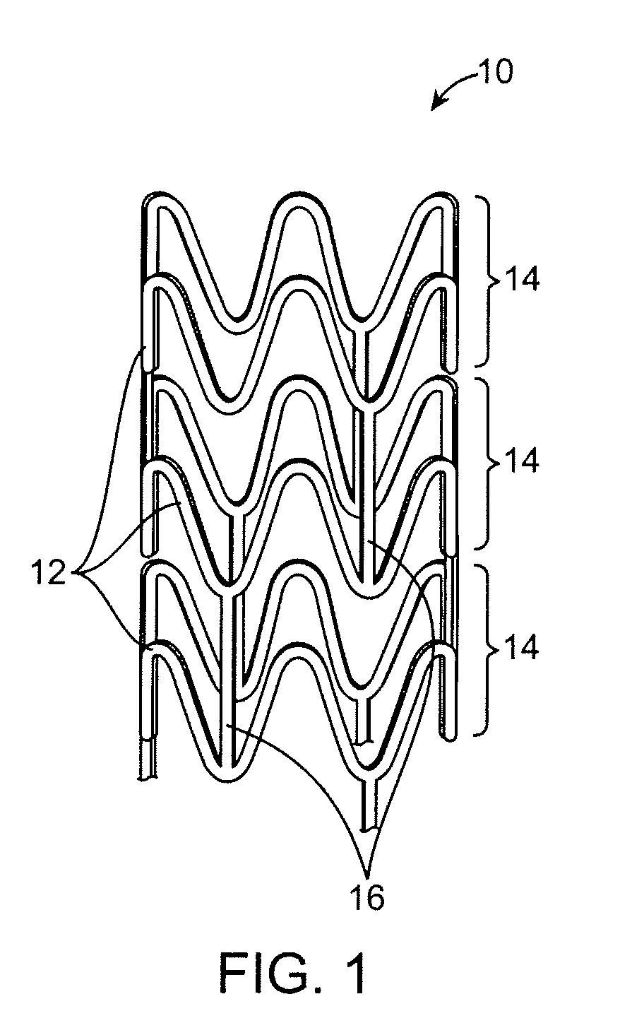
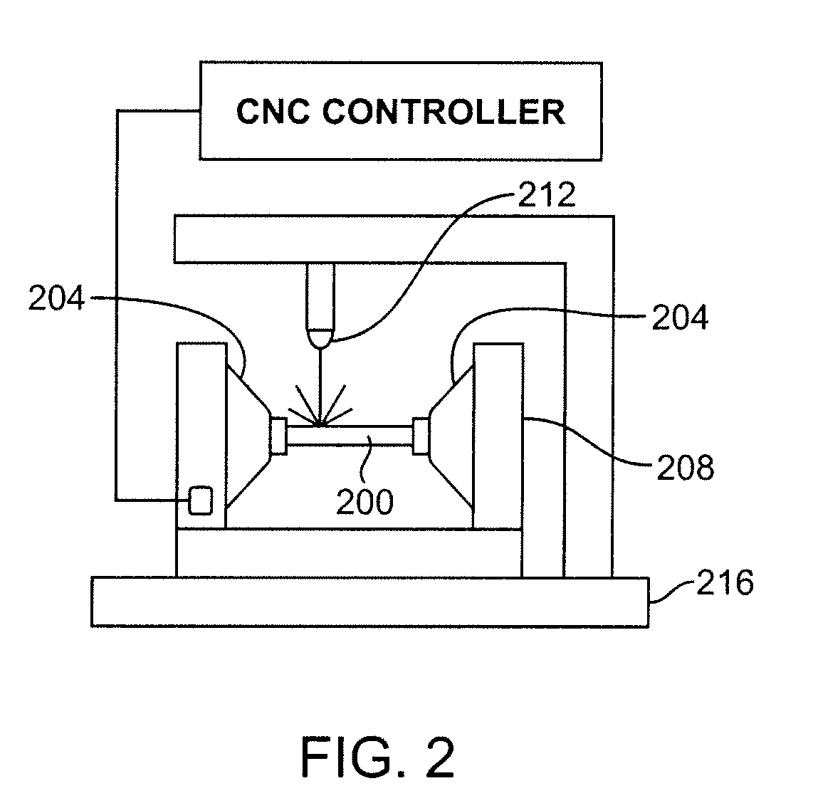
[0026]Embodiments of the present invention include methods of cooling a machined substrate during laser machining fabrication of a medical device to reduce or eliminate a heat affected zone. Embodiments also include making a medical device from a construct, such as a stent, that includes a therapeutic agent. Although the methods apply to any laser machining technique, the methods are particularly relevant to ultrashort-pulse laser machining of substrates. These embodiments are suitable for fabricating fine and intricate structures of implantable medical devices such as stents. “Ultrashort-pulse lasers” refer to lasers having pulses with widths or durations shorter than about a picosecond (=10−12). “Pulse width” refers to the duration of an optical pulse versus time. The duration can be defined in more than one way. Specifically, the pulse duration can be defined as the full width at half maximum (FWHM) of the optical power versus time.

[0027]Ultrashort-pulse lasers can include both p...


PUM

PropertyMeasurementUnit
outer diameteraaaaaaaaaa
lengthaaaaaaaaaa
peak poweraaaaaaaaaa

Abstract

Laser machining a tubular construct comprising a polymer layer to form a stent pattern in the construct with localized cooling of the machined surface to reduce or prevent heat transfer to uncut polymer of the polymer layer is disclosed.

Description

BACKGROUND OF THE INVENTION[0001]1. Field of the Invention[0002]This invention relates to laser machining techniques for fabricating medical devices.[0003]2. Description of the State of the Art[0004]This invention relates to laser machining of devices such as stents. Laser machining refers to removal of material accomplished through laser and target material interactions. Generally speaking, these processes include laser drilling, laser cutting, and laser grooving, marking or scribing. Laser machining processes transport photon energy into a target material in the form of thermal energy or photochemical energy. Material is removed by melting and blow away, or by direct vaporization / ablation.[0005]The application of ultrashort-pulse lasers for high quality laser material processing is particularly useful due to the extremely high intensity (>1012 W / cm2), ultrashort-pulse duration (<1 picosecond), and non-contact nature of the processing. Ultrashort pulse lasers allow precise an...

Claims


Application Information

Patent Timeline
Patent Type & Authority Applications(United States)
IPC IPC(8): B23K26/00
CPCA61F2/82A61F2240/001B23K26/4065B23K26/1417B23K26/0635B23K26/0624B23K26/146B23K2103/42B23K2103/50
Inventor HUANG, BINCASTRO, DANIEL A.OZKAN, ARZU M.
Owner ABBOTT CARDIOVASCULAR
Learn More