
Rotary bearing, rotary table device and table diameter determining method

a technology of rotary table and determining method, which is applied in the direction of bearing cooling, manufacturing tools, instruments, etc., can solve the problems that the practical implementation of machine tools has not been realized, and achieve the effects of high load-bearing performance, high speed rotation, and high rigidity

Inactive Publication Date: 2010-04-29
THK CO LTD
View PDF13 Cites 16 Cited by
  • Summary
  • Abstract
  • Description
  • Claims
  • Application Information

AI Technical Summary

Benefits of technology

The technical problem addressed in this patent is the difficulty of achieving high speed rotation, high rigidity, and high load-bearing performance in a rotary bearing used for a machine tool. The conventional machine tool driven with multi-spindle cannot sufficiently achieve the functions and effects based on the adoption of the direct driving structure. The present invention aims to provide a rotary bearing and a rotary table device capable of achieving appropriate cooling effect, simultaneously realizing high speed rotation, high rigidity, and high load-bearing performance of the rotary bearing utilized for a machine tool. The invention also provides a method for easily and properly determining diameter of a table of a new rotary table device.

Problems solved by technology

However, in the machine tool provided with both the three-axis drive mechanism and the rotary driving mechanism mentioned above includes many troublesome matters for a practical use or realization, and hence, such machine tool has not been realized in practical use

Method used


Image

  • Rotary bearing, rotary table device and table diameter determining method
  • Rotary bearing, rotary table device and table diameter determining method
  • Rotary bearing, rotary table device and table diameter determining method

Examples


first embodiment

[0039]Hereunder, a first preferred embodiment for embodying the present invention will be explained with reference to FIGS. 1 to 5. It is further to be noted that the first embodiment mentioned hereunder is not one limited to the invention according to respective patent claims, and that various combinations of the characteristic features explained in the first embodiment are not essential for the solution of the present invention.

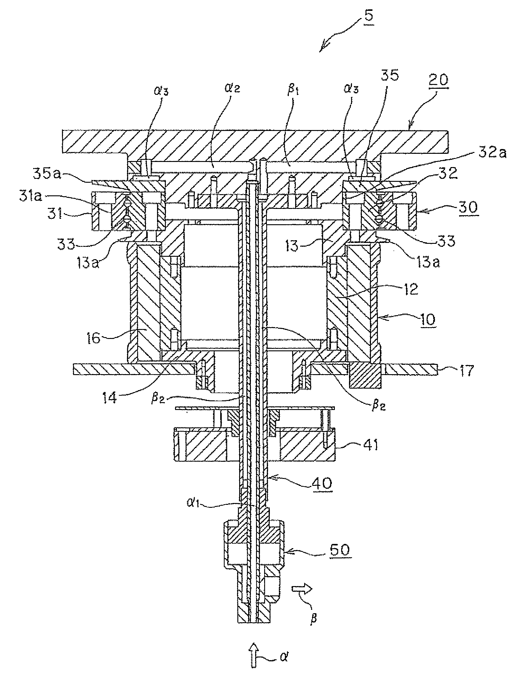
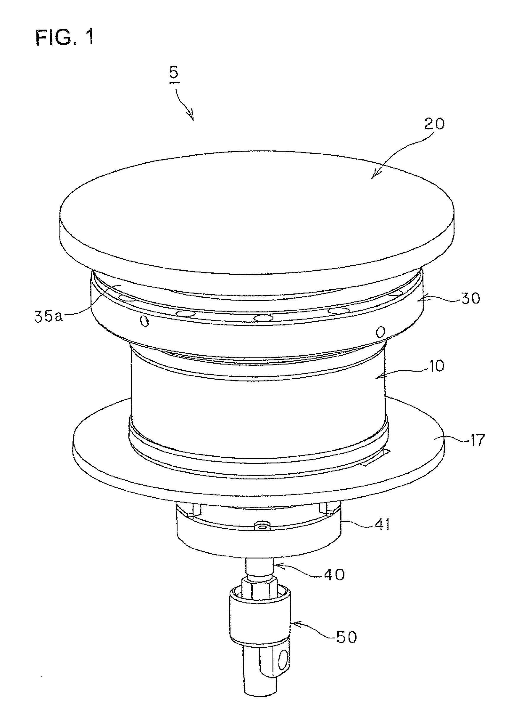
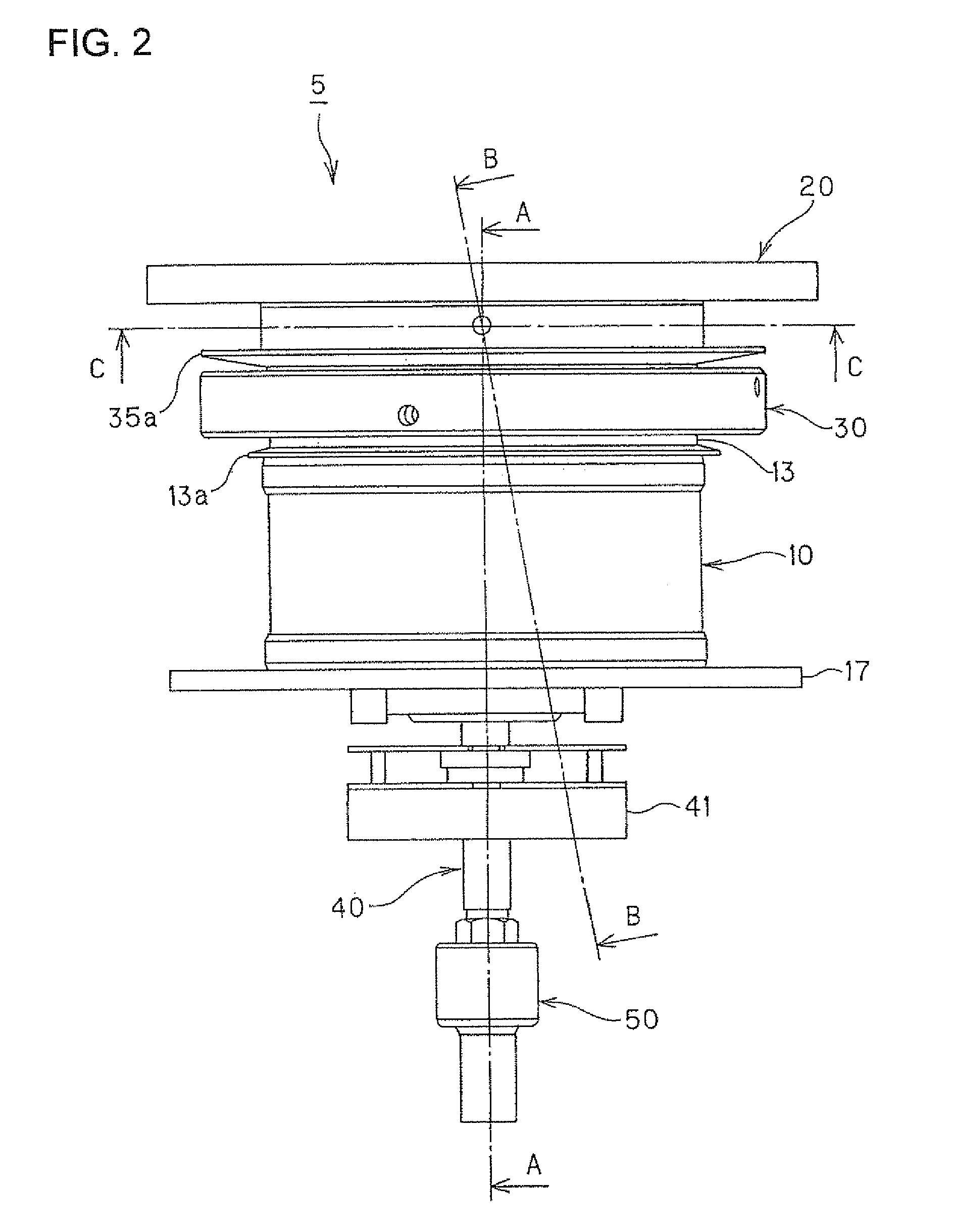
[0040]FIG. 1 is a perspective view showing an outer configuration of an entire structure of a rotary table device according to a first embodiment of the present invention. Further, FIG. 2 is a front view showing an entire structure of the rotary table device according to the first embodiment. FIG. 3 to FIG. 5 are sectional views explaining the specific structure of the rotary table device of the first embodiment, in which FIG. 3 is a sectional view, especially, of A-A section in FIG. 2, FIG. 4 is a sectional view, especially, of B-B section in FIG. 2, and F...

second embodiment

[0073]Hereunder, another preferred embodiment for embodying the present invention will be explained with reference to FIGS. 7 to 11. Further, it is to be noted that the following second embodiment is not limited to the invention of the respective patent claims and all the combination of the subject features described in the second embodiment is not absolutely essential for the achievement of the present invention.

[0074]FIG. 7 is a perspective view showing an outer appearance of an entire structure of a rotary table device according to the second embodiment of the present invention. FIG. 8 is a front view showing the entire structure of the rotary table device according to the second embodiment of the present invention. FIGS. 9 to 11 are sectional views for explaining the specific structure of the rotary table device according to the second embodiment of the present invention, and in particular, FIG. 9 is a sectional view taken along the line D-D in FIG. 8, FIG. 10 is a sectional vie...


PUM

PropertyMeasurementUnit
rotational driving forceaaaaaaaaaa
diameteraaaaaaaaaa
total lengthaaaaaaaaaa

Abstract

A rotary table device includes a hollow motor drive source, a table rotated thereby, and a rotary bearing supporting the table. The rotary bearing is provided an outer race having an inner surface to which a rolling surface is formed, an inner race having an outer peripheral surface to which a rolling surface opposing to the rolling surface of the outer race is formed, and a plurality of rolling members disposed in a rolling passage formed by the rolling surface of the outer race and the rolling surface of the inner race, and a cooling medium passage (α, β) is formed so as to be adjacent to either one of the inner race and outer race constituting a rotational driving side. According to the structure mentioned above, a rotary bearing and a rotary table device capable of achieving suitable cooling effect can be provided.

Description

TECHNICAL FIELD[0001]The present invention relates to a rotary bearing and a rotary table device specifically provided with a cool g structure. Furthermore, the present invention relates to a rotary table device and a table diameter determining method at a time of designing the rotary table device.BACKGROUND ART[0002]For example, in a technological field of a machine tool, there has been provided a machine tool commonly provided with a three-axis driving mechanism for moving a spindle portion for mounting a tool in X-axis, Y-axis and Z-axis directions and a rotary driving mechanism for rotating a support member, such as table, for supporting a workpiece to be worked around a C-axis and / or A-axis (for example, please refer to the following Patent Document 1). In such machine tool, the three-axis drive mechanism is driven by each of liner motors, and the rotary driving mechanism is driven by a hollow motor. More especially, the rotary driving mechanism more quickly starts to be driven...

Claims


Application Information

Patent Timeline
Patent Type & Authority Applications(United States)
IPC IPC(8): B23Q1/25F16C33/38G01B5/08
CPCB23Q11/127B23Q2210/004B23Q2220/004F16C37/007F16C2322/39
Inventor TANIGUCHI, SHIGERUTANAKA, TOSHIYAASO, TOSHIYUKI
Owner THK CO LTD
Learn More